Locking electrical adapter

a technology of electrical adapters and connectors, which is applied in the direction of coupling contact members, coupling device connections, coupling parts engagement/disengagement, etc., and can solve the problems of significant disruption of work in progress, interruptions are annoying and inconvenient for users, and the plug replacement significantly disrupts work

Inactive Publication Date: 2001-01-09
PHILLIPS DUANE A
View PDF21 Cites 76 Cited by
  • Summary
  • Abstract
  • Description
  • Claims
  • Application Information

AI Technical Summary

Problems solved by technology

Almost everyone who has ever used a hand mixer, vacuum cleaner, power tool, or other hand-manipulated electrical appliance has accidentally pulled the plug out of a wall outlet.
At best, such interruptions are annoying and inconvenient for the user, who has to stop work to re-insert the plug into the outlet before he can continue.
In some situations, replacing the plug significantly disrupts work in progress, as when a construction worker has to climb down a ladder to replace the plug, then climb back up to resume work.
Over time, repeated stress on the plug may damage the conductors to the point that the power cord must be replaced.
In some situations, damaged plugs and loose connections can lead to potentially dangerous sparking and electrical shorts.
Notwithstanding the wide variety of designs encompassed by the prior art, many presently-available locking connectors and adapters are relatively complex, correspondingly difficult and expensive to manufacture, and too delicate and breakage-prone for long-term household or industrial use.
Others can be used only with specially-designed sockets or wall outlets; these cannot be used with standard, general service outlets of the types prescribed by the National Electrical Code (NEC) or the American National Standards Institute (ANSI).

Method used


Image

  • Locking electrical adapter
  • Locking electrical adapter
  • Locking electrical adapter

Examples


Embodiment Construction

In the following detailed description, reference numerals are used to identify structural elements, portions of elements, surfaces and areas in the drawings. It should be understood that like reference numerals are intended to identify the same structural elements, portions or surfaces consistently throughout the several drawing figures, as such elements, portions or surfaces may be further described or explained by the entire written specification. As used in the following description, the terms "horizontal," "vertical," "left," right," "up," "down," as well as adjectival and adverbial derivatives thereof (e.g., "horizontally," "rightwardly," "upwardly," etc.) refer to the relative orientation of the illustrated structure as the particular drawing figure faces the reader. Similarly, the terms "inwardly" and "outwardly" refer to the orientation of a surface of revolution relative to its axis.

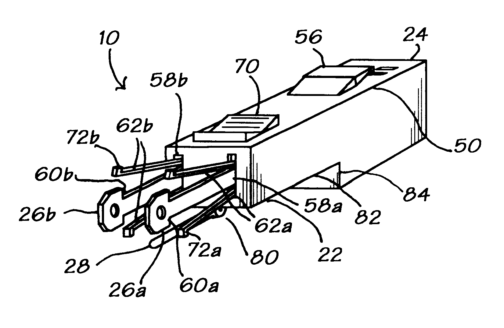
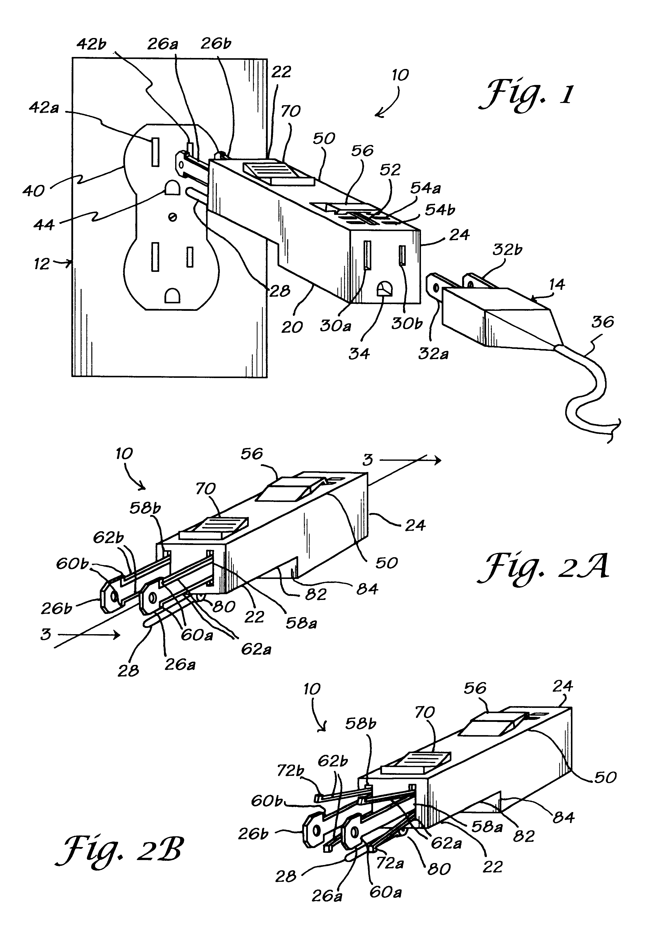
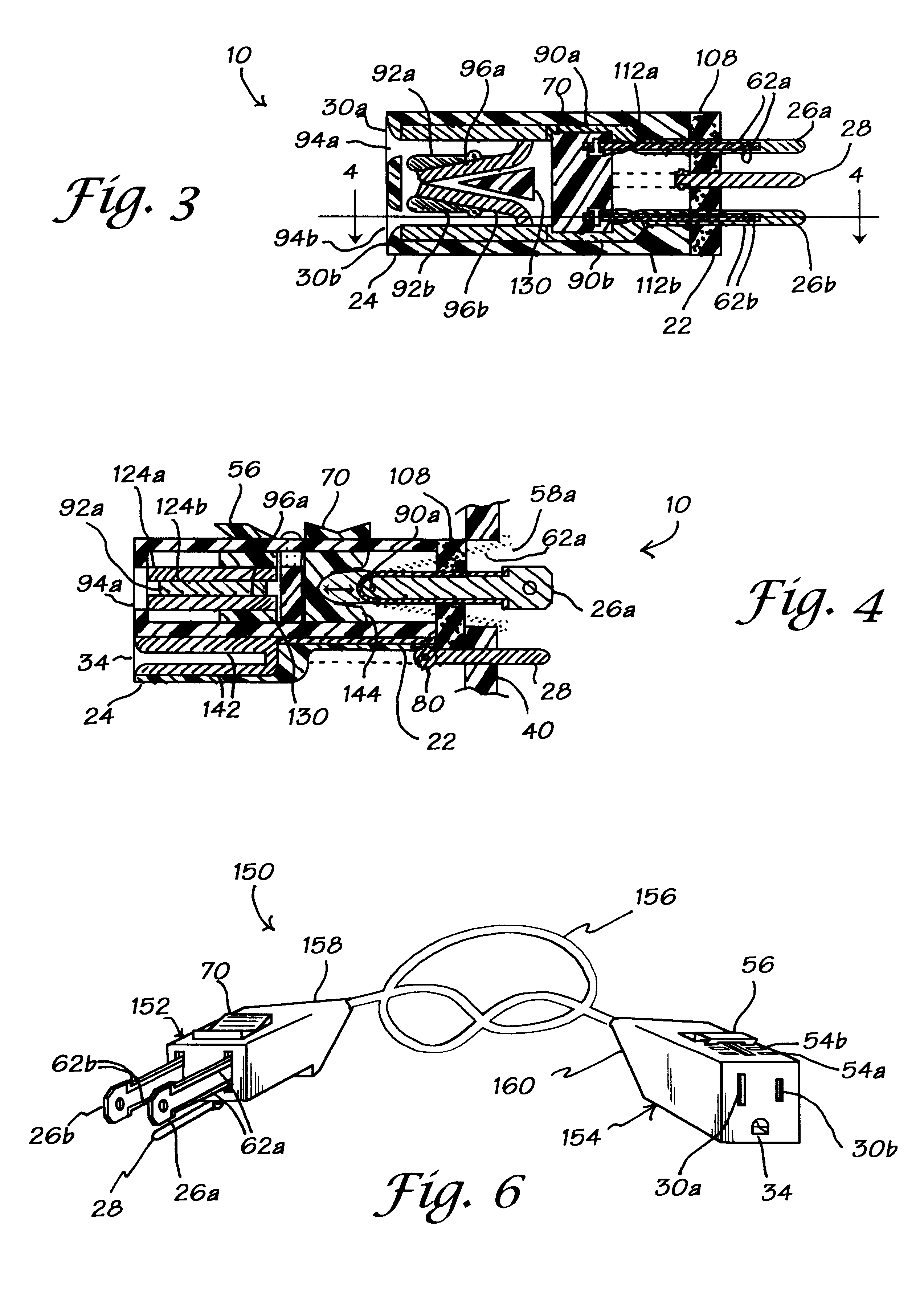
Referring now to FIG. 1, there is shown a locking electrical adapter or connector 10 accordi...


PUM


Abstract

An electrical adapter with dual, user-operable locking mechanisms for attachment to a standard electrical plug and outlet, one for securing the prongs of the adapter into a socket or wall-mounted outlet or receptacle and the other for securing a standard electrical plug thereto. The two mechanisms work independently of each other to secure the male and female sides of a conventional plug-and-socket combination together. The adapter can be used with existing appliances, hand tools, extension cords, and electrical outlets without the need for rewiring. The male and female ends of the adapter may be connected by an electrical cord to replace a conventional extension cord; alternatively, the locking mechanism can be built into replacement electrical plugs or a wall outlet having approximately the same dimensions as conventional outlets. Use of the invention eliminates the annoying problem of power interruptions to appliances, hand tools, and the like that occur when a plug is accidentally pulled loose from its socket. The invention also provides extra safety from electrocution and reduces spark hazards by locking the plug and socket together to help prevent accidental dislodging.

Description

1. Field of the InventionThe present invention relates to a locking connector and adapter for interfacing a standard electrical plug to a receptacle. In particular, the present invention relates to an adapter having two independent, releasable locking mechanisms, the first mechanism for securing the prongs of an electrical plug therein and the second mechanism for securing the adapter to a standard receptacle.2. Discussion of BackgroundInadvertent removal of an electrical plug from a socket, outlet strip, or wall-mounted receptacle has been a matter of concern since electrical appliances became common. Almost everyone who has ever used a hand mixer, vacuum cleaner, power tool, or other hand-manipulated electrical appliance has accidentally pulled the plug out of a wall outlet. At best, such interruptions are annoying and inconvenient for the user, who has to stop work to re-insert the plug into the outlet before he can continue. In some situations, replacing the plug significantly d...

Claims


Application Information

Patent Timeline
Patent Type & Authority Patents(United States)
IPC IPC(8): H01R13/02H01R13/193H01R13/20H01R31/06
CPCH01R13/193H01R13/20H01R31/06
Inventor PHILLIPS, DUANE A.
Owner PHILLIPS DUANE A
Why Eureka
Try Eureka