Apparatus and method for aligning shaft couplings

a technology of shaft couplings and apparatuses, applied in the direction of couplings, screws, rod connections, etc., can solve the problems of equipment damage, vibration and other problems, coupling deflection, etc., to prevent damage to the coupling, precise alignment, and more precise alignment

Inactive Publication Date: 2001-01-09
FERGUSON LESLIE W
View PDF6 Cites 13 Cited by
  • Summary
  • Abstract
  • Description
  • Claims
  • Application Information

AI Technical Summary

Benefits of technology

According to yet another preferred embodiment of the invention, the cam pin includes a stop collar for being positioned on the large diameter segment of the cam pin for preventing damage to the coupling.
According to yet another preferred embodiment of the invention, a cam pin is provided for precisely aligning bolt holes in first and second adjacent drive shaft couplings, and comprises a cam pin for being positioned in generally aligned bolt holes in the shaft couplings and rotated to bring the bolt holes in to more precise alignment. The cam pin includes a first, relatively large diameter segment having a cylindrical wall defining a first longitudinal axis for being positioned in a precisely fitting condition in the bolt hole of the first coupling, and a second, relatively small diameter segment having a cylindrical wall defining a second longitudinal axis offset from and eccentric to the longitudinal axis of the first segment for being relatively loosely positioned in the generally aligned bolt hole of the second coupling. Rotation of the cam pin within the bolt holes within which it is positioned progressively varies the overall diameter of the cam pin to bring the bolt holes into alignment for installation of the connecting bolts.
A method for precisely aligning bolt holes in first and second adjacent drive shaft couplings in accordance with

Problems solved by technology

Operation outside of these recommended norms can cause damage to equipment, vibration and other problems.
Connecting pins cause deflection of the couplings due to binding with time required to

Method used


Image

  • Apparatus and method for aligning shaft couplings
  • Apparatus and method for aligning shaft couplings
  • Apparatus and method for aligning shaft couplings

Examples


Embodiment Construction

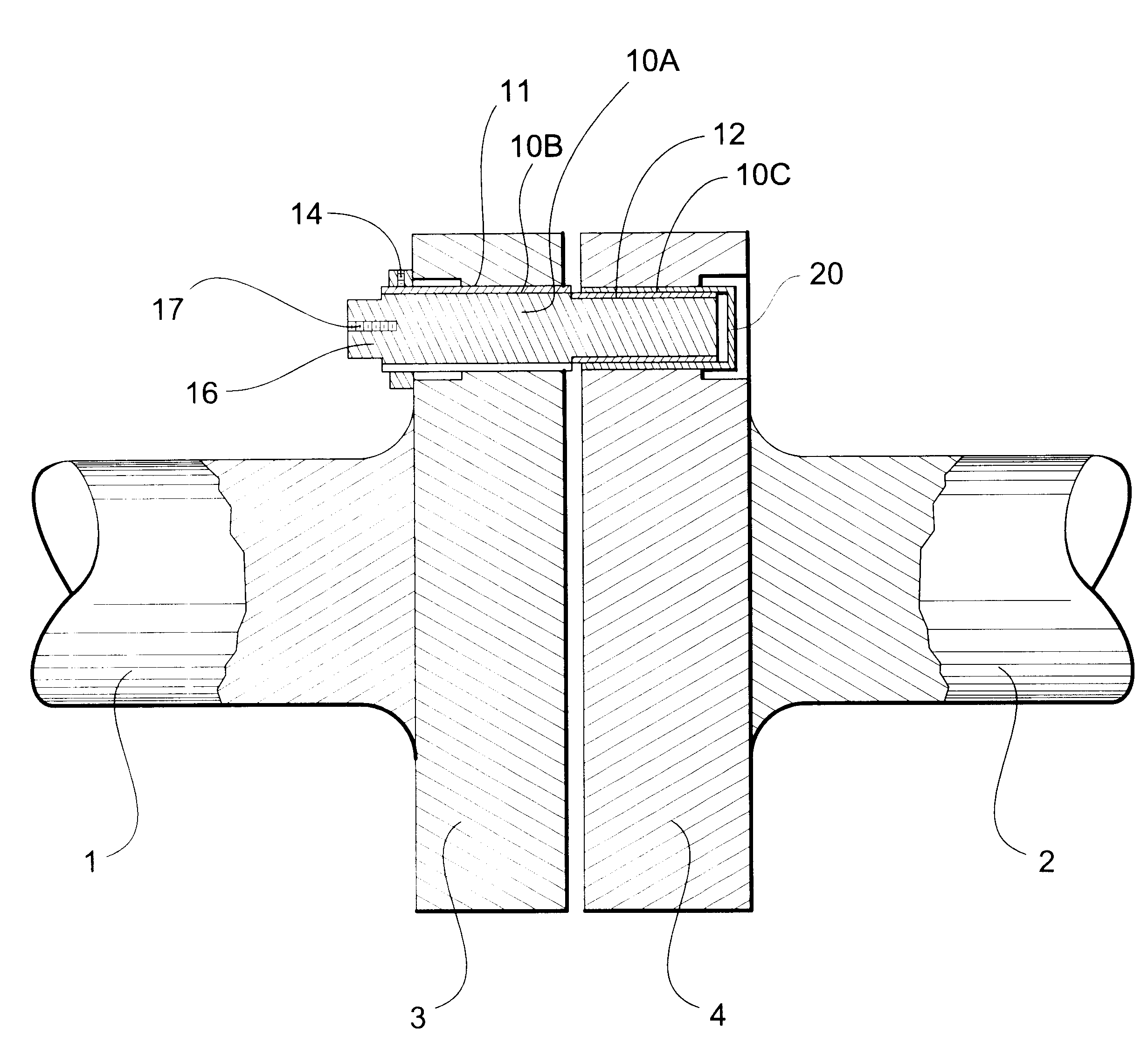
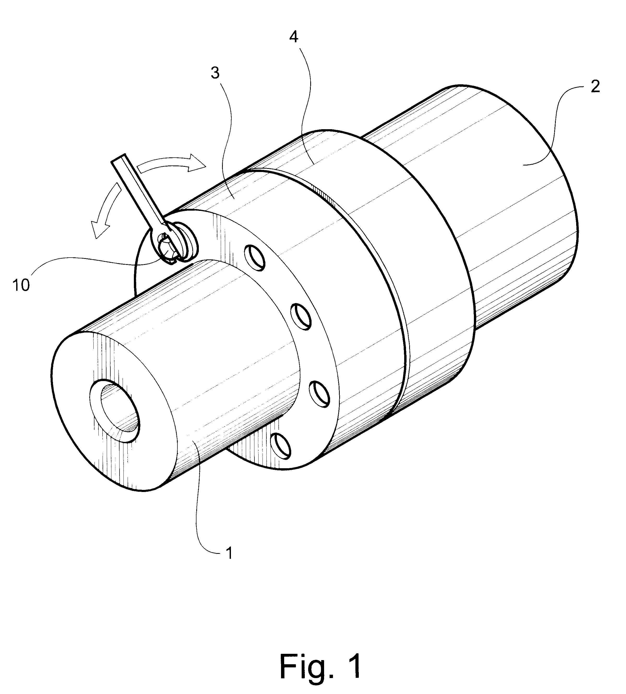
Referring now specifically to the drawings, FIG. 1 illustrates a typical arrangement whereby two aligned, rotatable shafts, such as power plant turbine shafts, 1 and 2 are joined by respective enlarged end couplings 3 and 4. Each of the end couplings 3 and 4 include axially-extending bolt holes 5 spaced at regular intervals around their respective peripheries. During operation, the couplings 3 and 4 are joined by bolts extended through aligned ones of the bolt holes 5 and secured by properly torqued bolts (not shown) in a conventional manner. As is also shown in FIG. 1, a cam pin 10 according to the present invention is positioned in one selected pair of bolt holes and manipulated in the manner disclosed below.

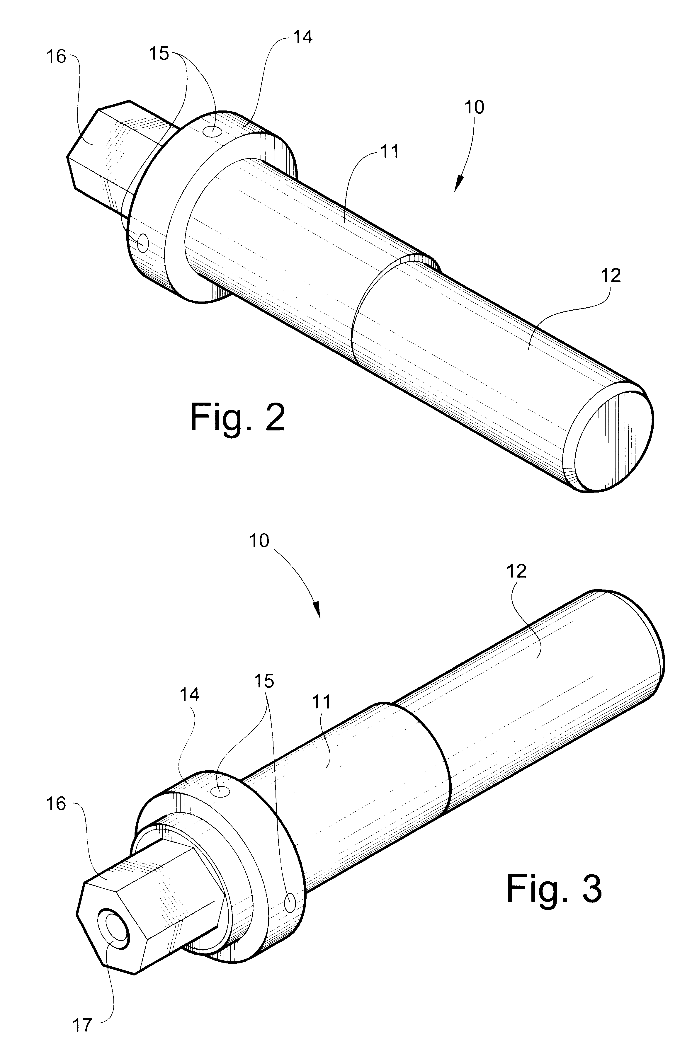
Referring now to FIGS. 2 and 3, cam pin 10 includes a first, relatively large diameter segment 11 having a cylindrical wall which defines a first longitudinal axis. The large diameter segment 11 of the cam pin 10 is positioned in a precisely fitting condition in the bolt hole ...


PUM

PropertyMeasurementUnit
Thicknessaaaaaaaaaa
Diameteraaaaaaaaaa

Abstract

An apparatus for precisely aligning bolt holes in first and second adjacent drive shaft couplings, including a cam pin for being positioned in the generally aligned bolt holes in the shaft couplings and rotated to bring the bolt holes in to more precise alignment. The cam pin includes a first, relatively large diameter segment having a cylindrical wall defining a first longitudinal axis for being positioned in a precisely fitting condition in the bolt hole of the first coupling, and a second, relatively small diameter segment having a cylindrical wall defining a second longitudinal axis offset from and eccentric to the longitudinal axis of the first segment for being relatively loosely positioned in the generally aligned bolt hole of the second coupling. A cam sleeve is provided for being positioned in axial and rotational sliding relation over the small diameter segment of the cam pin and within the bolt hole of the second coupling. The cam sleeve has an offset bore defining a progressively varying wall thickness whereby rotation of the cam pin and cam sleeve relative to each other and to the bolt holes within which they are positioned brings progressively varies the overall diameter of the cam pin to bring the bolt holes into precise alignment for installation of the connecting bolts.

Description

TECHNICAL FIELD BACKGROUND OF THE INVENTIONThis invention relates to an apparatus and method for aligning couplings of rotating shafts, particularly large, high speed shafts such as used in electric power plants and other large industrial operations. Manufacturers of high speed rotating equipment provide specifications for desired alignment and limits of deviation. Operation outside of these recommended norms can cause damage to equipment, vibration and other problems. Manufacturers also require a process that rotates both shafts to record the alignment relationship between the two rotors. Each rotor can be rotated separately or the rotors can be temporarily connected with soft metal pins. The rotation of each coupling separately requires additional time to rotate each rotor. Connecting pins cause deflection of the couplings due to binding with time required to free the pins. Neither process will stop the coupling rims with the correct degree position to allow use of new laser align...

Claims


Application Information

Patent Timeline
IPC IPC(8): B25B27/16B25B27/14F16D1/033F16D1/02
CPCB25B27/16F16D1/033Y10T29/49895Y10T29/53917Y10T403/1616Y10T403/68Y10T403/645
Inventor FERGUSON, LESLIE W.
Owner FERGUSON LESLIE W
Why Eureka
Try Eureka