
Lighting module with a light guide for a motor vehicle

Inactive Publication Date: 2001-01-16
VALEO VISION SA
View PDF6 Cites 22 Cited by
  • Summary
  • Abstract
  • Description
  • Claims
  • Application Information

AI Technical Summary

Benefits of technology

In order to overcome the above mentioned drawbacks, the present invention is directed to a lighting module in which conduction of the light flux between the real light source and each facet of the light guide is individualized, in such a way that the illumination of the facets can be controlled, and the desired final light beam obtained; and in which a system is provided for mounting the light guide in such a way as to ensure accurate positioning of the facets and output face of these elements in relation to the dioptric elements, so that the latter will project, in the emission direction, images corresponding to the well-positioned facets in the light beam, as well as good positioning of the input face of the light guide with respect to the light source.
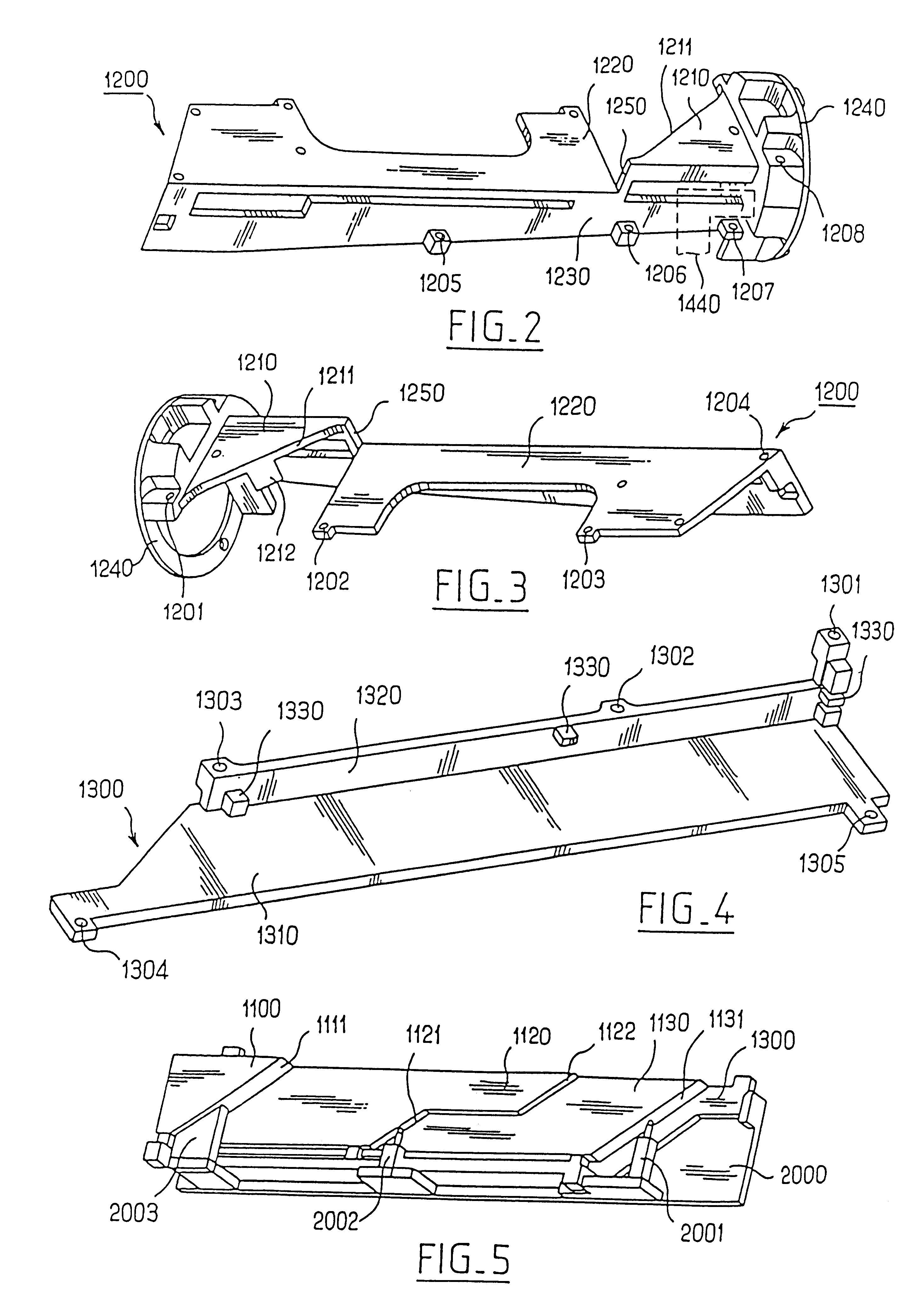
Thus, the invention has the advantage that the transparent strips constituting the light guide are in engagement in two horizontal and vertical reference planes defined by the flat first and second portions of the reference member. This avoids the optical problems associated with manufacturing tolerances in the transparent strips, because the reflective facets of the strips are positioned in a predetermined way with reference to the horizontal reference plane, and their output faces are likewise positioned in a predetermined way with reference to the vertical plane.
Thus the invention affords the advantage, due to the mounting member at the front or output side of the module, that accurate positioning of the dioptric elements (for example Fresnel lenses) and masks can be ensured with respect to the front or output faces of the transparent strips. In addition, because the masks and the dioptric elements are fixed to the same mounting member, they keep their relative position in spite of displacements which may be induced by any possible dispersion or spreading effects. In this connection, in that case it is the assembly consisting of the masks and the dioptric elements fixed to each other that is displaced. The relative position of the images of the masks therefore does not vary, and the cut-off of the beam remains the same.

Problems solved by technology

Such a headlight, however, have the disadvantage that it is not possible to control the quantity of light flux arriving at each of the facets of the single optical barrel, because of the multiple reflections of the light rays within the latter.
In this regard, because of the uncontrollable multiple reflections of the light rays within the barrel, it can happen that one or more facets of the barrel are very weakly illuminated.
In addition, in such a headlight, no mounting means is provided for ensuring accurate positioning of the oblique reflective facets and of the output face of the light guide with respect to the lenses, such that the latter will project, in the emission direction, images corresponding to the facets at a predetermined position, despite the dispersions of light within the thickness of the transparent barrel.
In addition, no means is provided for ensuring accurate positioning of the input face of the light guide with respect to the light source itself.

Method used


Image

  • Lighting module with a light guide for a motor vehicle
  • Lighting module with a light guide for a motor vehicle
  • Lighting module with a light guide for a motor vehicle

Examples


Embodiment Construction

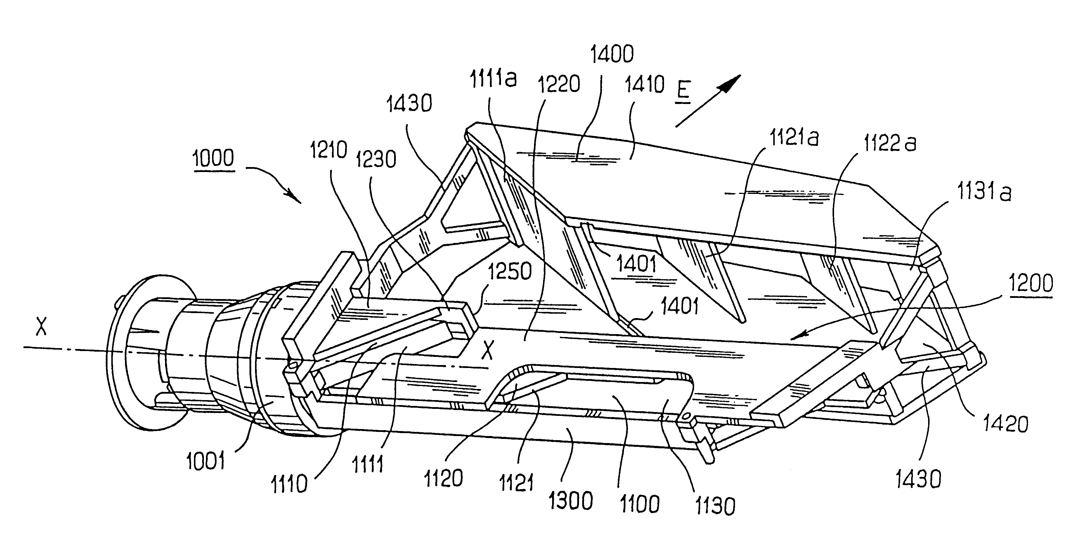
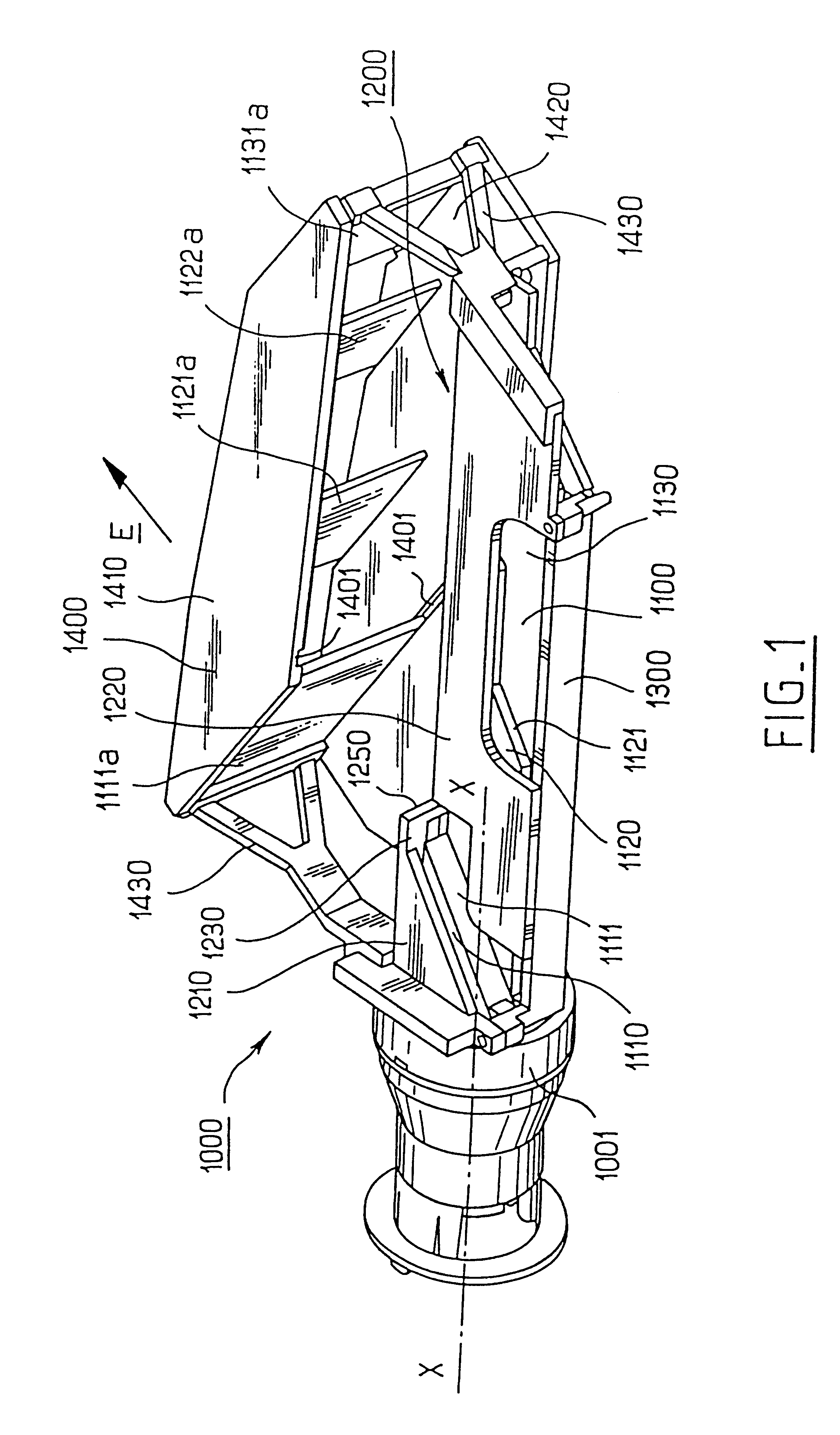
FIG. 1 shows a lighting module 1000 for a motor vehicle, which comprises a "real" light source, i.e. a source generating light when energized with power, together with means 1001 for concentrating the light radiation issued from the light source on one end of a light guide 1100.

The means for concentrating the light radiation emitted from the light source consists essentially of a reflector, or elliptical mirror, 1001. The light source itself (not visible in the drawings) consists of the filament of a motor vehicle lamp, which is mounted in the housing seen at the left-hand end of FIG. 1, and which is preferably disposed in the axis of the elliptical reflector 1001 at one of its foci. The light flux from the light source is reflected by the reflector 1001 in a set of rays which converge to the focal zone of the second focus of the elliptical reflector.

The light guide 1100, for guiding the light in the lighting module 1000, comprises a plurality of oblique reflective facets 1111, 1121...


PUM


Abstract

A lighting module for a motor vehicle headlight, in which light from a light source is received by the input end of a light guide having a plurality of oblique facets, which are reflective by total reflection and cooperating with lenses.The light guide comprises a set of transparent strips stacked together, and the module includes a reference member comprising a first portion which defines a horizontal reference plane, and a second portion which defines a vertical reference plane. The stacked transparent strips are abutted against these two portions of the reference member in a predetermined position on the longitudinal axis of the light guide, so that their facets will cooperate with the lenses to project in the emission direction images corresponding to the facets.

Description

The present invention relates to headlights for motor vehicles.It is known, from French patent specification FR 2 514 105 of the Company Valeo Vision, to provide a headlight which a light guide consists of a single transparent barrel arranged horizontally and transversely to the direction of emission, with the front of the barrel having a vertical outlet face for emitting light, and the rear of the barrel including a set of cut-outs of limited height defining a series of oblique reflective facets. These facets are disposed in an optical cooperating relationship with lenses having an axis parallel to the emission direction, so that the lenses project images corresponding to the facets in that direction.Such a headlight, however, have the disadvantage that it is not possible to control the quantity of light flux arriving at each of the facets of the single optical barrel, because of the multiple reflections of the light rays within the latter. In this regard, because of the uncontroll...

Claims


Application Information

Patent Timeline
IPC IPC(8): B60Q1/00F21V8/00F21S8/12F21S8/10F21V7/00
CPCB60Q1/0011F21S48/1241G02B6/001F21S41/24
Inventor BUARD, PHILIPPE
Owner VALEO VISION SA
Learn More