

Composite coated jaw faces
a technology of jaw face and coating, applied in the field of composite coated jaw face, can solve the problems of additional clamp pressure, instrument down time, additional expense,
- Summary
- Abstract
- Description
- Claims
- Application Information
AI Technical Summary
Problems solved by technology
Method used
Image

Examples
examples
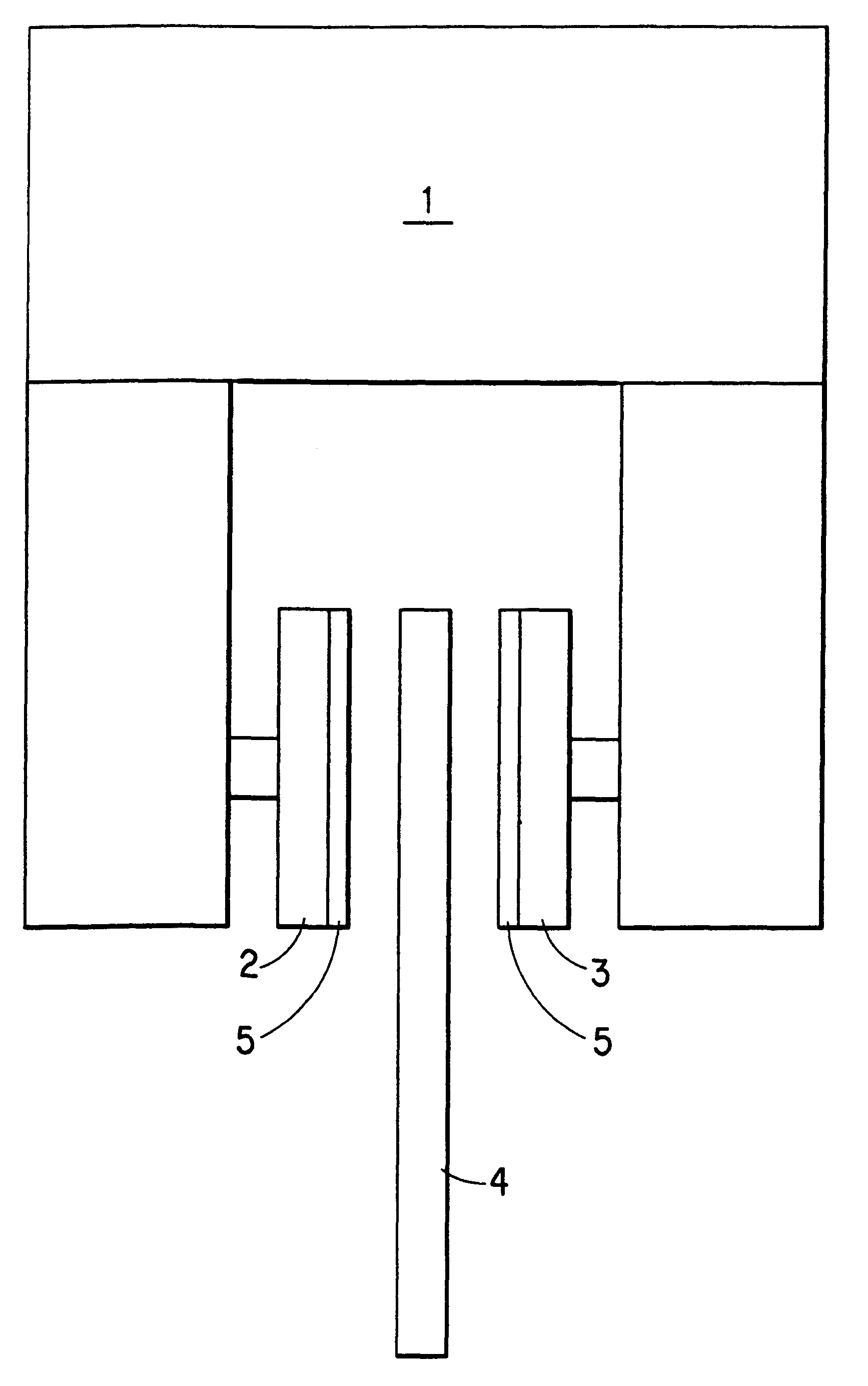
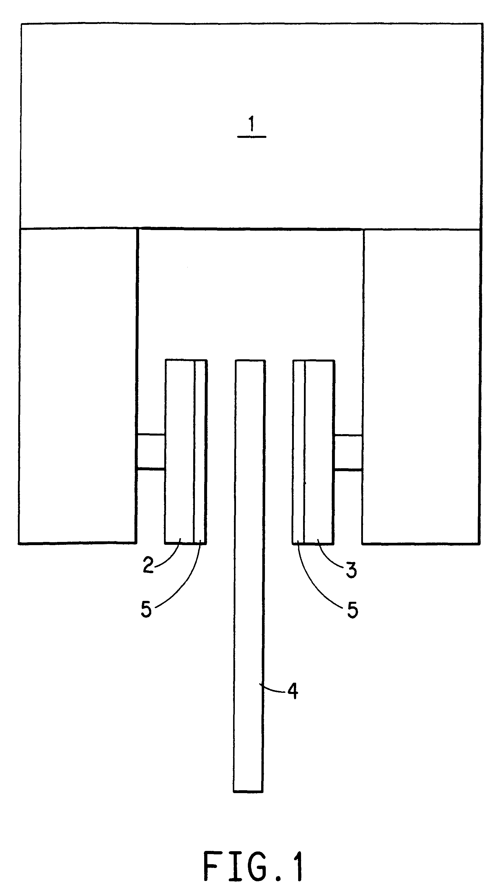
The method for coating the faces is described as follows:
Materials
Miller Stephenson Epon 828 epoxy resin
Miller Stephenson Versamid 140 catalyzing agent
DuPont Tedlar.RTM. release film
Plastic beaker 500 ml for mixing
Wooden tongue depressors for mixing
DuPont Kevlar.RTM. spun lace 2 oz / yd
Clamp faces for grips (oxide blasted w 65 grit alum oxide at 65 psi 2 to 3 passes
Procedure
A piece of release film was cut to approximate size of 12.times.12". A batch of resin-catalyst was mixed at 60 / 40 ratio resin to catalyst. After being thoroughly mixed, the resin and catalyst mixture was poured onto a sheet of film and spread evenly to form a "puddle" about the size of a piece of spunlace Kevlar.RTM.). The spunlace Kevlar.RTM. was then placed onto the resin which diffused into the spunlace Kevlar.RTM.. Once this process was complete, the clamp faces were laid very carefully onto the wetted material. There was no pressure applied to the faces. These were allowed to sit 24 hours so the resin system a...
PUM
 Abstract
Description
Claims
Application Information