
Transcription system kit

a transcription system and kit technology, applied in the field of recording writing system, can solve the problems of large volume, large whiteboard system of related art, large volume, and large volume of passive electronic board,

Inactive Publication Date: 2001-01-23
MIMIO
View PDF106 Cites 52 Cited by
  • Summary
  • Abstract
  • Description
  • Claims
  • Application Information

AI Technical Summary

Benefits of technology

Further according to this embodiment, the stylus and / or the writing element may include electronics which causes a signal to be transmitted by the stylus which identifies the stylus and / or the writing element as being compatible with the transcription system. In this regard, the stylus and / or the writing element may include logic for producing encoded identification signals, the transcription system also including logic for recognizing the encoded identification signals. By incorporating this feature, use of styluses and writing elements incompatible with the transcription system can be prevented by the system.
According to any of the stylus embodiments, the stylus housing may include an aperture which allows a user to rotate a writing element about its longitudinal axis housed within the stylus housing without having to disassemble the stylus housing or remove the writing element from the stylus housing. It is noted that some writing elements include a tip which is not symmetrical about the longitudinal axis of the writing element, such as a wedge shaped tip of a marker. In such instances, it may be desirable to periodically alter the angular positioning of the tip of the writing element This may be accomplished by rotating the writing element through the aperture without having to remove the writing element from the stylus housing or having to disassemble the stylus.
According to any of the stylus embodiments, the stylus may include a mechanism for distinguishing between different writing elements by only permitting a particular type of writing element (for example, based on color) to be positioned within the housing. In one variation, the writing element may have a shaped portion associated with a particular color, such as the end of the element opposing the tip. Meanwhile, the mechanism in the housing may have a shape which only allows a writing element having a particular shaped portion to fit within the housing, thereby preventing other types of writing elements from being positioned within the housing. This embodiment is useful for allowing a set of styluses to be color coded.
According to any of the stylus embodiments, the stylus may further include a cap removably attachable to the stylus housing distal end and sized to cover the portion of the writing element which extends from the stylus housing distal end. The cap preferably forms a seal with the stylus housing to prevent the writing element from drying out. The cap may be formed of a material which allows a user to observe the color of the writing element without having to remove the cap. For example, the cap may optionally be clear or opaque. Also the position signal transmitter may be positioned adjacent the distal end of the stylus housing and the cap may be sized to fit over the position signal transmitter.
According to this kit embodiment, the computer readable medium may include logic which allows a user to specify what function is performed by the transcription system in response to the stylus contacting a particular control section.

Problems solved by technology

The passive electronic boards tend to use large, expensive, board-sized photocopying mechanisms.
As described above, whiteboard systems of the related art are large, cumbersome, expensive and immobile.
Meanwhile, the mechanism in the housing may have a shape which only allows a writing element having a particular shaped portion to fit within the housing, thereby preventing other types of writing elements from being positioned within the housing.
However, such a cap design could damage a position signal transmitter 58 positioned on the stylus neck 118.
Further, traditional caps do not include the volume required to accommodate the position signal transmitter 58.
When this condition is met for some predetermined number of cycles, an error condition has occurred.
Another source of error can result from sudden variations in the system.
As a result, a large number of non-matching inquiry signals can be transmitted and a maximum of only two data points will be lost in the process of identifying the implement.

Method used


Image

  • Transcription system kit
  • Transcription system kit
  • Transcription system kit

Examples


Embodiment Construction

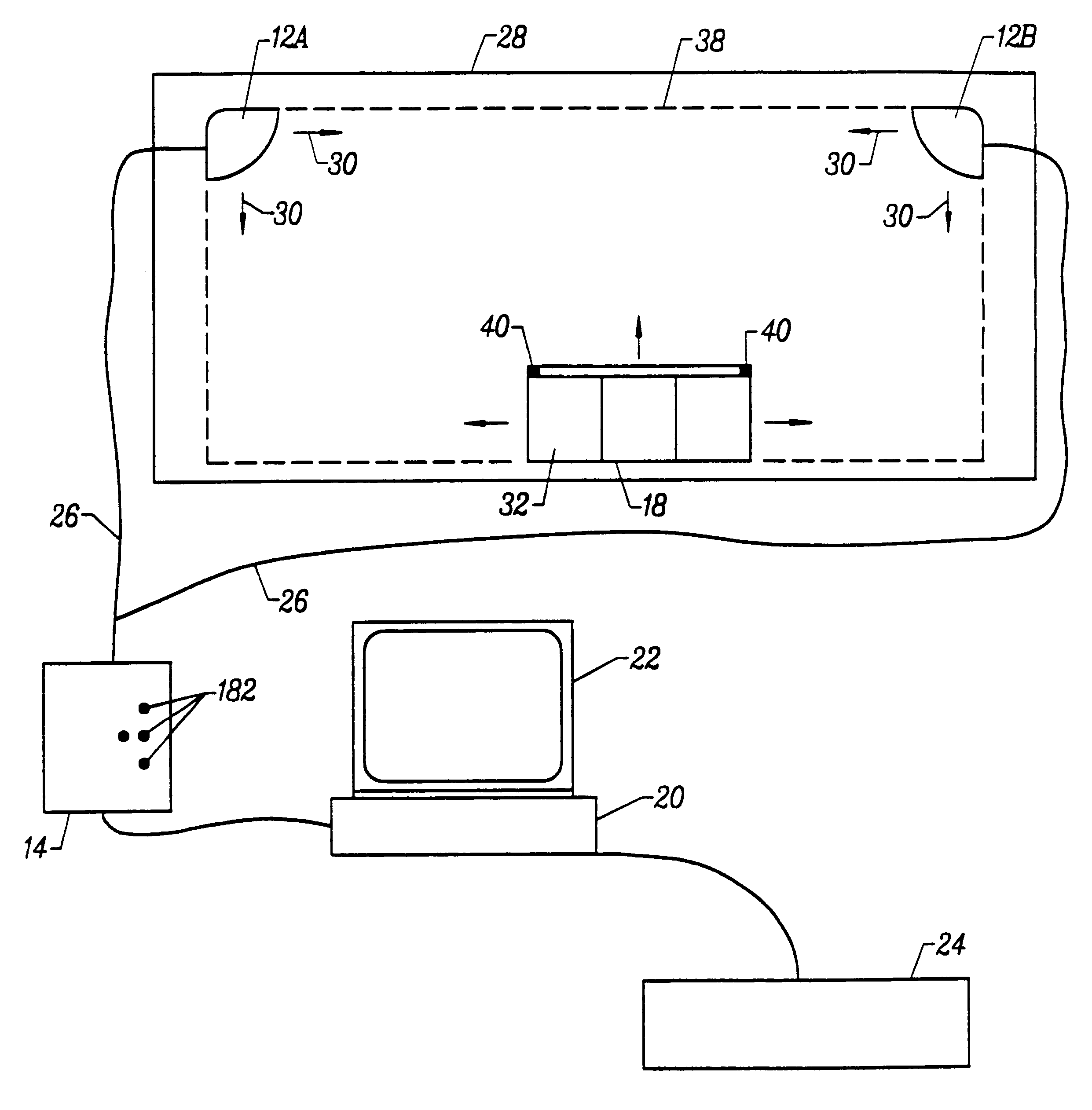
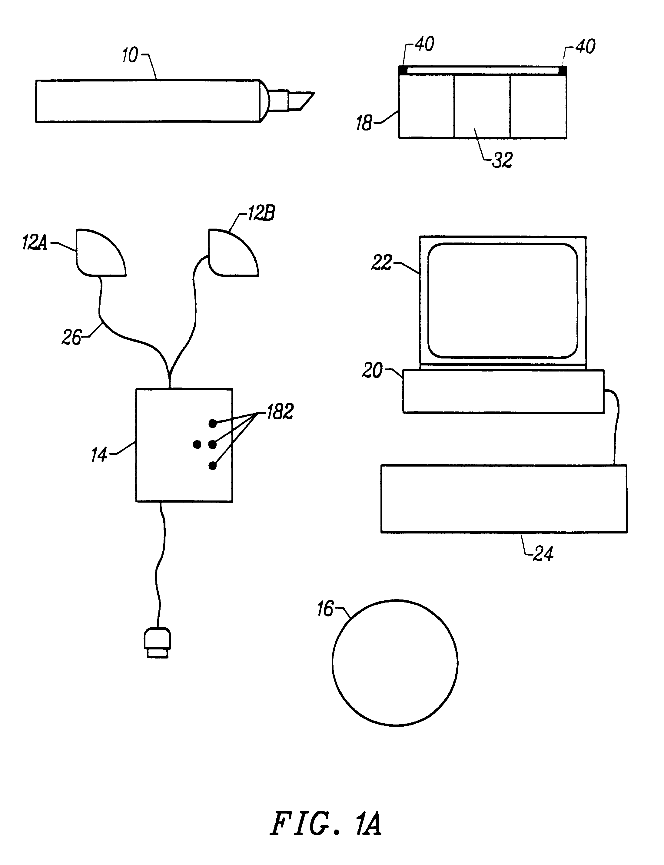
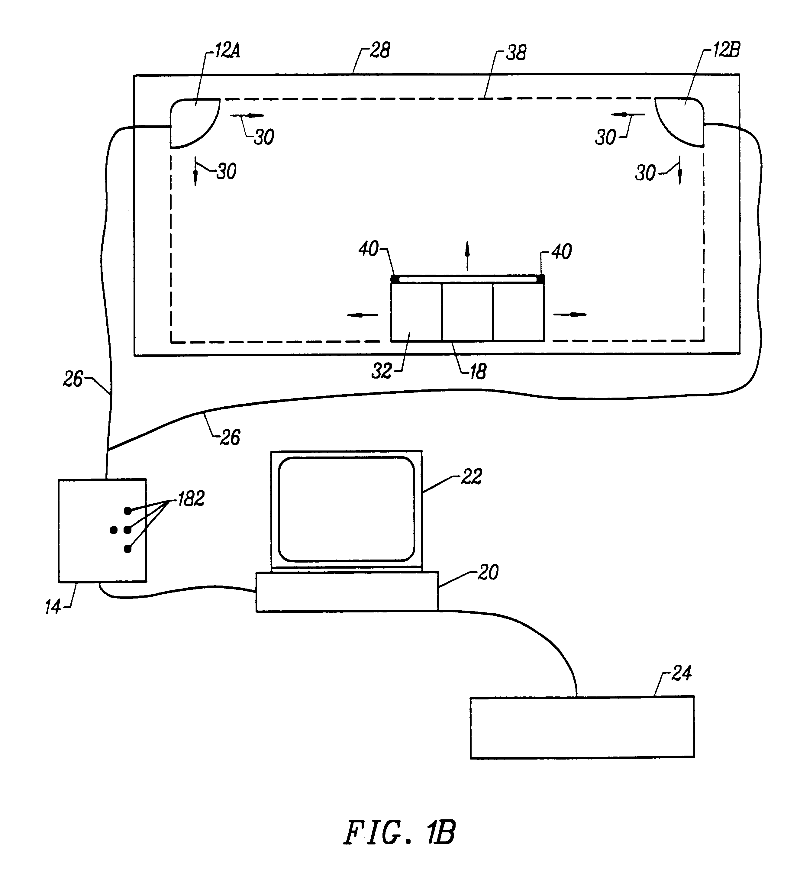
The following is an example of a transcription system according to the present invention, its contents and operation. FIG. 21 illustrates a transcription system kit. As illustrated, the kit includes a detector assembly 512, a set of styli 514, a set of whiteboard markers 516, an eraser 518, and a template 520.

FIG. 22 illustrates a stylus 514 which has been taken apart so that a marker 516 can be placed within the stylus 514. As illustrated, the stylus 514 includes a stylus body 522 which houses a AAA battery 524 and an ultrasound transmitter 526 adjacent a writing end 528 of the stylus. The stylus 514 also includes a side cover 530 which is sufficiently clear or translucent such that one can see the marker 516 through the side cover 530. The stylus 514 also includes a cap 532 which is sufficiently clear or translucent such that one can see a writing tip of the marker 516 through the cap 532.

FIGS. 23A and 23B illustrate a stylus 514 containing a marker 516. FIG. 23A illustrates a sid...


PUM


Abstract

A kit for use with a transcription system which includes a plurality of signal receivers for positioning adjacent a writing surface and for receiving one or more position signals transmitted from a stylus when the stylus is positioned adjacent the writing surface, the signal receivers producing timing signals in response to receiving position signals from the stylus, the kit comprising: a template coupleable to the writing surface, the template including one or more control sections; and a computer readable medium including logic for detecting when the stylus contacts a particular control section based on receipt by the signal receivers of one or more position signals transmitted from the stylus and logic for causing a function to be performed by the transcription system in response to detecting that the stylus has contacted the particular control section.

Description

1. Field of the InventionThe invention relates to a system for recording writing performed on a surface and its components and related methods where the position of a stylus used in the system to write on the surface is tracked using signals.2. Description of Related ArtExisting technologies for capturing and storing handwritten notes include digitized writing surfaces such as electronic whiteboards or SMARTBOARD.TM.. These electronic whiteboards typically either photocopy an entire writing surface or serve as the actual input device (e.g. an electronic template) for capturing the handwritten data. The whiteboards may be active or passive electronic devices where the user writes on the surface with a special stylus. The active devices may be touch sensitive, or responsive to a light or laser pen wherein the whiteboard is the detector that detects the active signal. The passive electronic boards tend to use large, expensive, board-sized photocopying mechanisms.As described above, whi...

Claims


Application Information

Patent Timeline
IPC IPC(8): G06F3/033G06F3/041G06F3/043
CPCG06F3/03545G06F3/0418G06F3/043G06F3/0433
Inventor CHERY, YONALDKELLEY, III, ANDREWMOYNE, WILLIAM P.VERMINSKI, MATTHEW D.
Owner MIMIO
Learn More