Piezoelectric actuator or motor, method therefor and method for fabrication thereof

a technology of actuators and motors, applied in piezoelectric/electrostrictive/magnetostrictive devices, electrical devices, piezoelectric/electrostrictive devices, etc., can solve the problems of limiting the development of existing products, difficulty in achieving a sufficient stroke of individual actuator elements, and the need for expensive high-precision assembly of elements and other parts in the system

Inactive Publication Date: 2001-02-06
PIEZOMOTORS UPPSALA
View PDF23 Cites 113 Cited by
  • Summary
  • Abstract
  • Description
  • Claims
  • Application Information

AI Technical Summary

Benefits of technology

Another object of the present invention is to provide a motor or actuator which can be further miniaturised.
A further object of the present invention is to provide a motor or actuator, which can achieve a large range of combined motions.

Problems solved by technology

When going to miniature motors, this technique will be disadvantageous, since the movements become too small and limited by a non-controllable surface topography etc.
There are some crucial factors limiting the development of existing products based on the non-resonance step principle.
Among the limits there is the difficulty of achieving a sufficient stroke of the individual actuating elements and the need for a costly high precision assembly of the elements and other parts in the system.
This is a fairly time consuming operation and therefore costly.
The disadvantage with a single clamped bimorph is that the force capacity is greatly reduced in comparison with an ideal lever, which is the reason why these types of elements normally are used for positioning when there is no considerable need for forces.
However, no completely satisfying design for these leverage structures has been presented yet.
Either they are too expensive to produce (for instance assembling) or the performance is not sufficient.
The problem is how to control the shape of a long narrow tube.
Either the motion is too slow, the tube too weak or results in too much heating.
Present microfabrication techniques are rather expensive and yet far from suited for making cheap active components.

Method used


Image

  • Piezoelectric actuator or motor, method therefor and method for fabrication thereof
  • Piezoelectric actuator or motor, method therefor and method for fabrication thereof
  • Piezoelectric actuator or motor, method therefor and method for fabrication thereof

Examples


Embodiment Construction

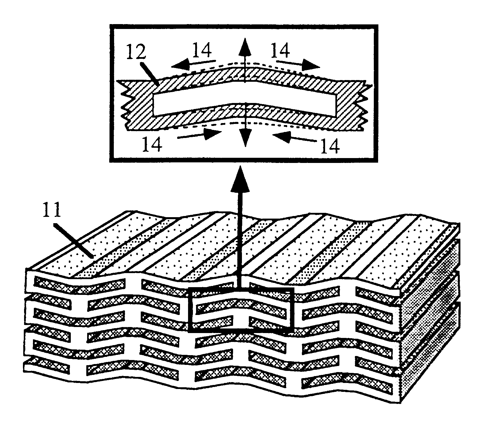
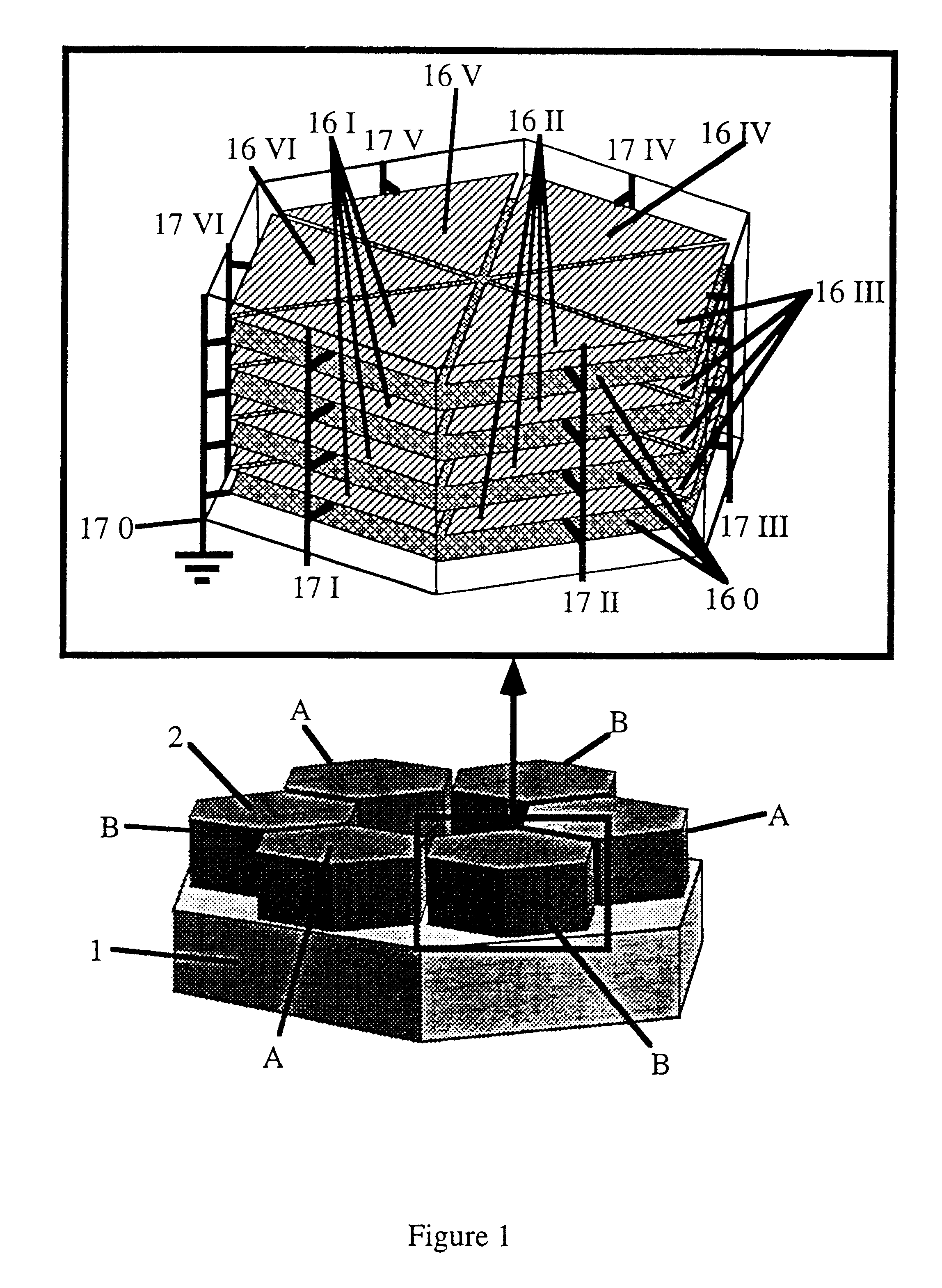
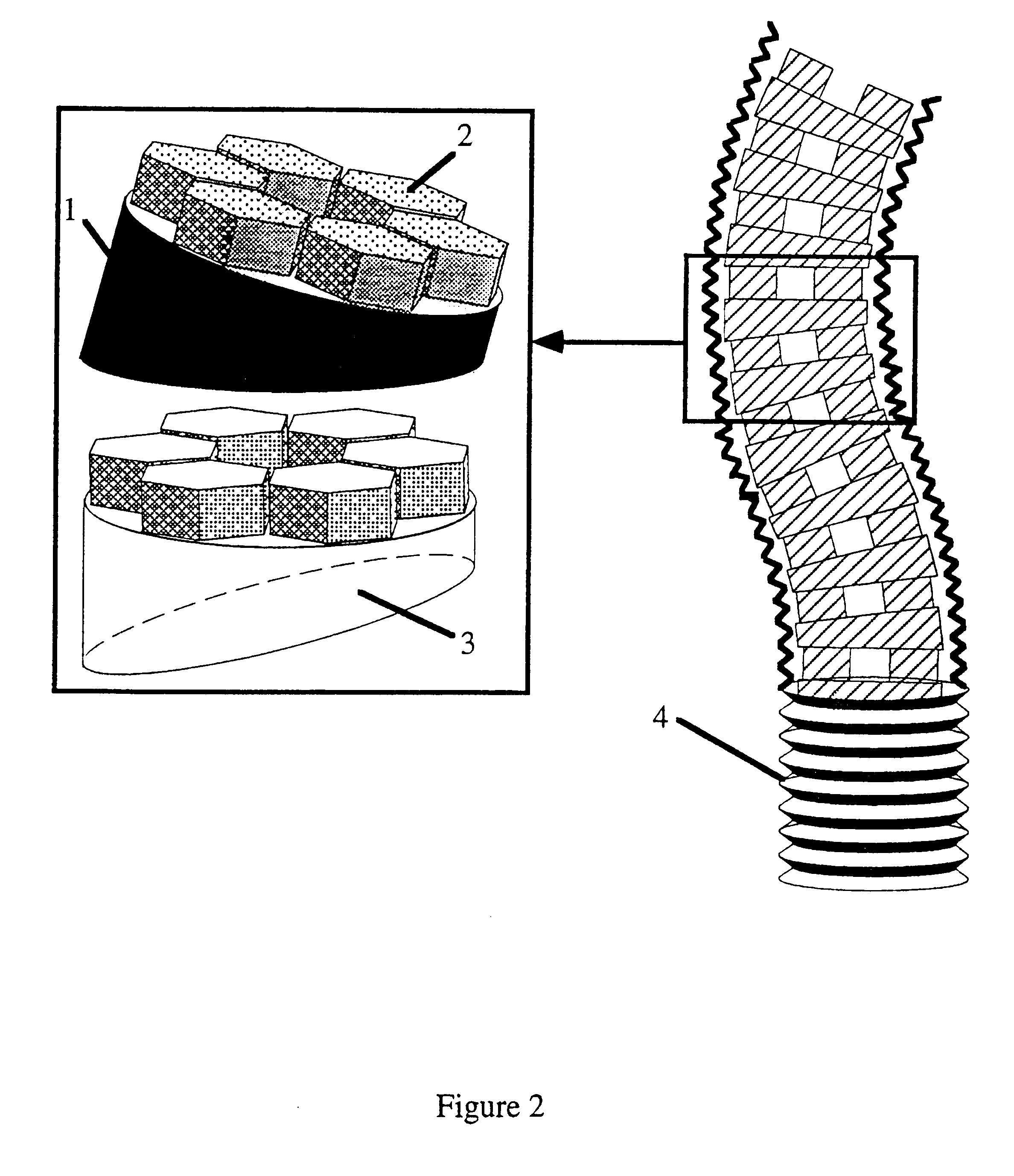
A preferred embodiment of the invention is illustrated in FIG. 1, which discloses a monolithic module integrating all the active elements. The monolithic module can be described in terms of a larger hexagonal mechanically passive part 1 and active elements 2, which are integral parts of the module. Therefore none of the parts shown in FIG. 1 are possible to dismount, since they together form the monolithic module. The active elements 2 are arranged to be in contact with, or at least in the vicinity of the surface of the body which is supposed to be moved relative to the module (not shown in the figure).

Each element 2 consists of an electromechanical material, preferably piezoelectric, which typically is a multilayered structure. An electromechanical material responds to a certain electrical field applied across it. In order to have a large shape change upon applying the voltage, the electrical field in each portion of the material has to be high. For a non-layered material, a single...


PUM


Abstract

This invention relates to an actuator or motor comprising an electromechanical material which alters its shape under the influence of an electrical voltage. Said actuator comprises at least a monolitic module (1,2) with electrodes integrated in said electromechanical material and in that the force or displacement due to the applied voltages is transferred, to the point to be actuated or moved by the shape change of the material, using at least two independent contact points. The invention also relates to a method for fabricating said actuator or motor.

Description

The invention relates to small motors and actuators comprising electro-mechanical materials which alters its shape under the influence of an electric field. In particular the invention relates to motors and actuators in which the motion relative another body is created by repetition of small steps. The invention also relates to a method of driving such motors and to a method for manufacturing the motors.RELATED ARTThere is a great need for high performance motors in the size range below a few millimeters, motors of the kind which should be able to create linear and / or rotating motion. It is often desirable that this kind of motors both have a high precision and can exert large forces. One may realize that since reliable and cheap motors of this kind is requested for e.g. driving cameras, hard disks, CD-players etc the potential market is huge. Also in the area of medical instrumentation, e.g. pumps, such motors are of great interest.In the state of the art, various devices based on ...

Claims


Application Information

Patent Timeline
Patent Type & Authority Patents(United States)
IPC IPC(8): H01L41/083H01L41/09H02N2/00H02N2/02
CPCH01L41/0906H01L41/042H01L41/0831H01L41/0833H01L41/0835H02N2/0095H10N30/503H10N30/202H02N2/02H10N30/501H10N30/505
Inventor JOHANSSON, STEFANBEXELL, MATS
Owner PIEZOMOTORS UPPSALA
Why Eureka
Try Eureka