Control circuit driven by a differential input voltage and method for controlling same

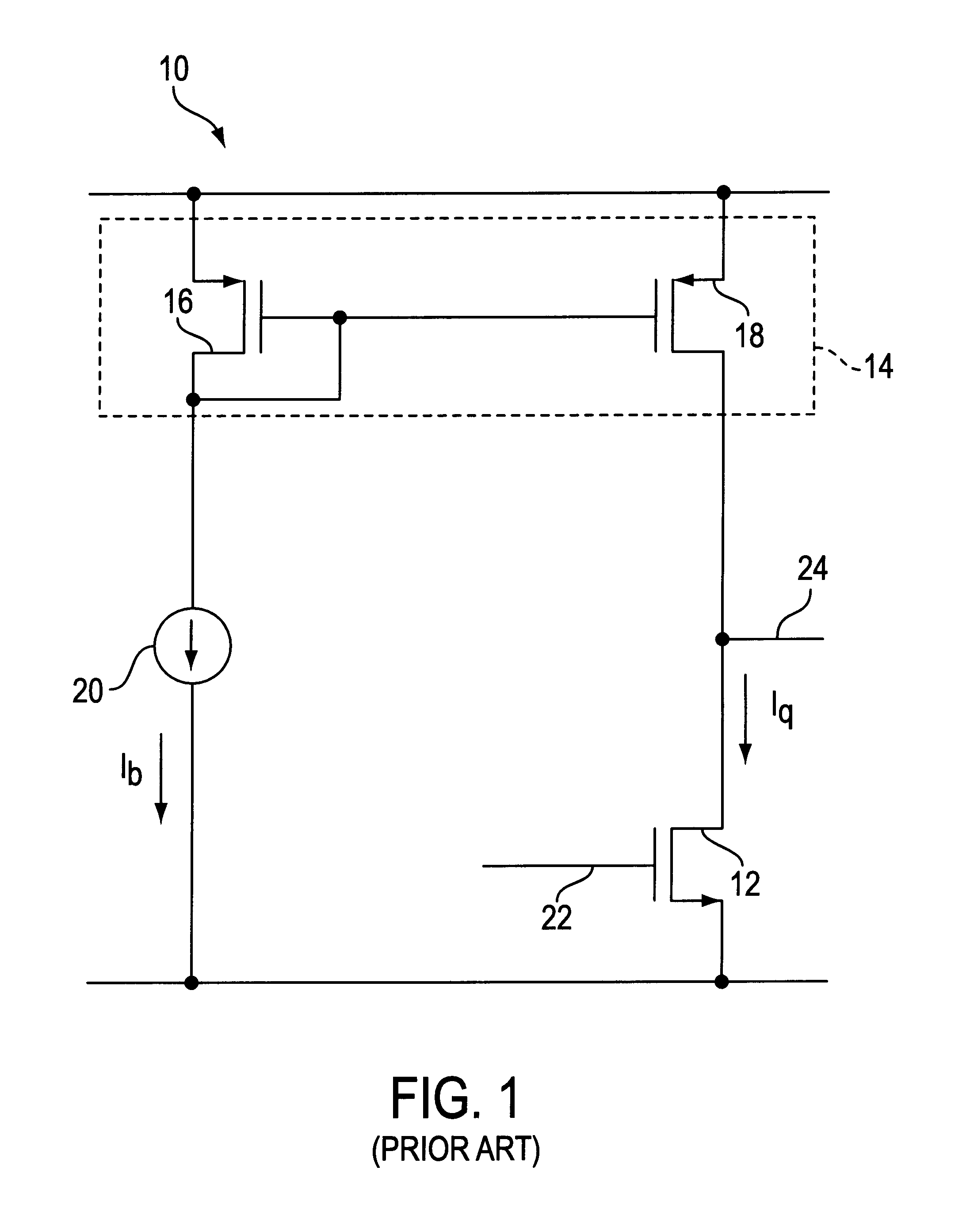
a control circuit and input voltage technology, applied in the field of electronic circuits, can solve the problems of not allowing the output voltage to swing close to either supply, the output stage 10 creates significant distortion, and the load transistor 18 provides no symmetrical drive for sourcing output curren

Inactive Publication Date: 2001-02-06
GAINTECH
View PDF6 Cites 21 Cited by
  • Summary
  • Abstract
  • Description
  • Claims
  • Application Information

AI Technical Summary

Problems solved by technology

However, load transistor 18 provides no symmetrical drive for sourcing output current.
Consequently, output stage 10 creates significant distortion while providing a maximum output voltage swing.
Although the class AB complementary output stage 30 is beneficial when a wide bandwidth, low distortion circuit having high output current is required, it does not allow the output voltage to swing close to either supply.
However, the additional amplification stage embodied in the second npn transistor 52 introduces its own problems.
However, there has been very little development in circuitry that has the requirements of both a high bandwidth circuit and a low power circuit.

Method used


Image

  • Control circuit driven by a differential input voltage and method for controlling same
  • Control circuit driven by a differential input voltage and method for controlling same
  • Control circuit driven by a differential input voltage and method for controlling same

Examples


Embodiment Construction

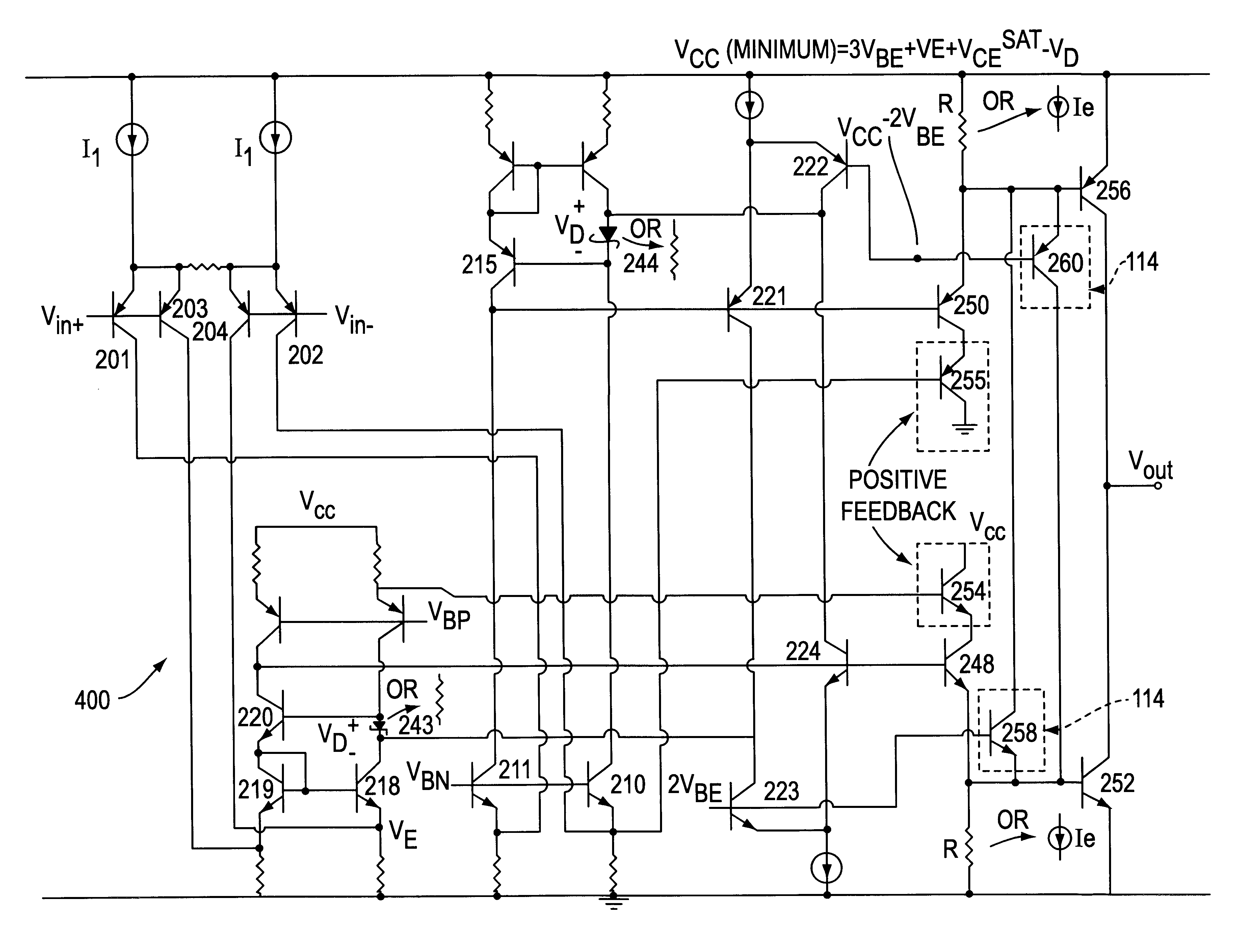
Although the Darlington output stage allows greater output current when low quiescent supply current is required, problems will arise when the Darlington configuration is used in a low voltage, high speed circuit that requires low distortion. The present invention addresses these problems by using dual signal paths to drive complementary push-pull output stages.

FIG. 4 shows a block diagram of an amplifier 100 in accordance with one embodiment of the present invention. The amplifier 100 includes a dual input stage 110 including input stages 101 and 102, and a complementary push-pull output stage 112 having two push-pull output stages 104 and 106 connected at their outputs. Each input stage 101 and 102 has a differential input voltage V.sub.IN+ and V.sub.IN-. Each stage also has a single-ended output used to drive a common-emitter push-pull transistor configuration in the dual push-pull output stage 112. Two substantially symmetrical signal paths are formed from the common differentia...


PUM


Abstract

The present invention teaches a variety of output stages for amplifying high speed signals while keeping distortion low and using a low supply voltage. The invention includes the use of dual complementary signal paths that include a complementary push-pull output stage. Bias circuits are used to keep the paths symmetrical and positive feedback is used to oppose output loading effects.

Description

DESCRIPTION1. Technical FieldThe present invention is related to electronic circuits for amplifying electrical signals. In particular, the present invention teaches a variety of power amplifying output stages, control circuits for such stages, and methods for controlling these devices.2. Background ArtAmplification circuitry can be loosely divided into two types: high bandwidth and low power amplification circuitry. In the creation of high bandwidth and low power amplification circuitry, designers have different goals in mind and thus concern themselves with different issues when designing the different types of circuitry.For example, in the design of high bandwidth circuitry, designers are concerned with achieving high frequency and low distortion. However, most high bandwidth circuitry applications are not concerned with power efficiency issues. Thus, maintaining a low quiescent current or operating with a low supply voltage generally are not design constraints in high bandwidth c...

Claims


Application Information

Patent Timeline
Patent Type & Authority Patents(United States)
IPC IPC(8): H03F1/38H03F1/30H03F3/30H03F3/45
CPCH03F1/307H03F1/38H03F3/3067H03F3/45107H03F2203/45648H03F2203/45676
Inventor SOMERVILLE, THOMAS A.
Owner GAINTECH
Why Eureka
Try Eureka