Eureka AIR delivers breakthrough ideas for toughest innovation challenges, trusted by R&D personnel around the world.

Infrared selective reflective polarizing element

a reflective element and selective technology, applied in the field of polarizing elements, can solve the problems of excessively restricting the view through the window, unable to meet the needs of users, and devices that are not particularly useful,

Inactive Publication Date: 2001-02-06
3M INNOVATIVE PROPERTIES CO
View PDF105 Cites 57 Cited by
  • Summary
  • Abstract
  • Description
  • Claims
  • Application Information

AI Technical Summary

Benefits of technology

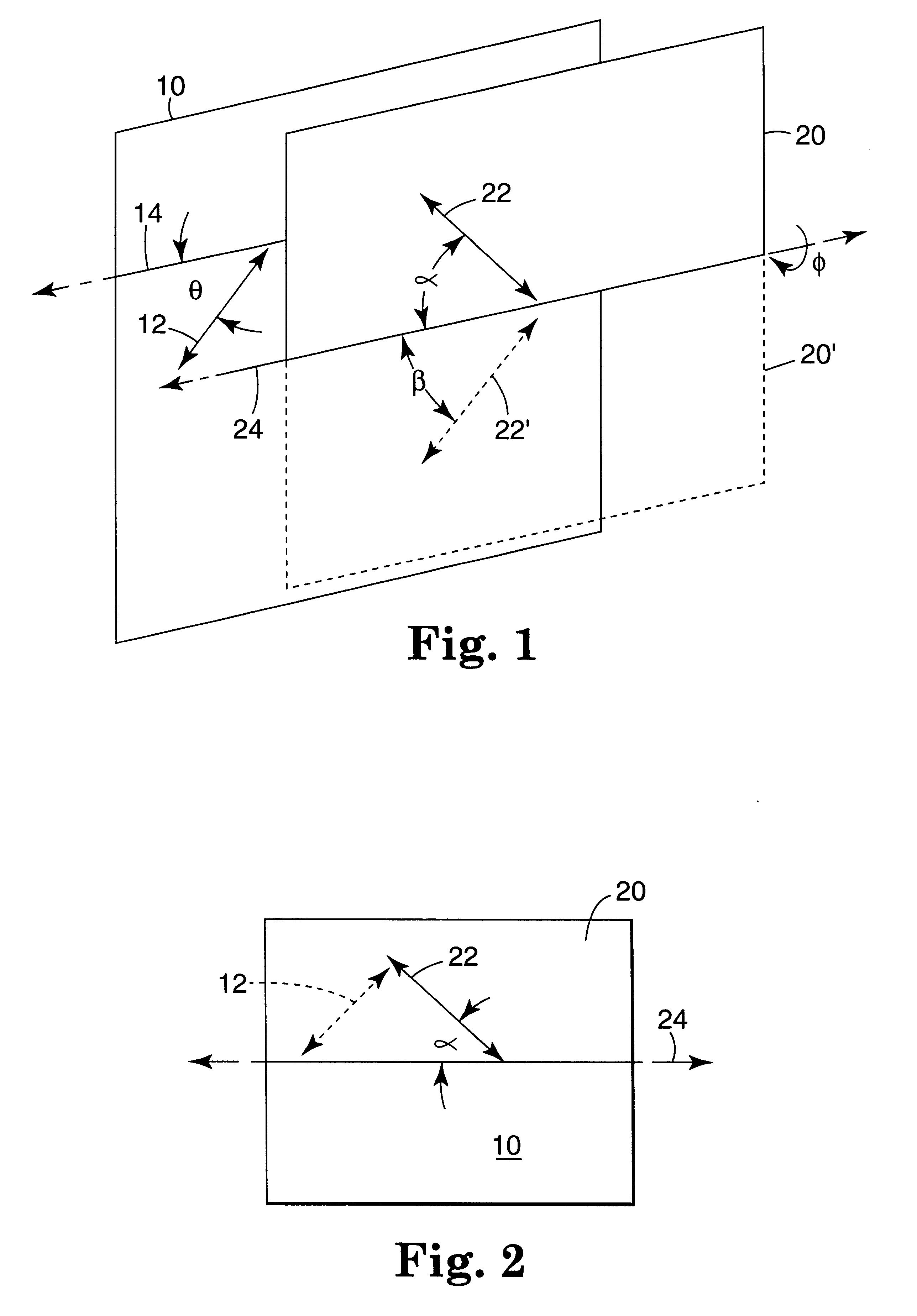
In another aspect, the present invention provides a light valve including a first polarizing element having a first transmission axis; and a second polarizing element having an axis of rotation and a second transmission axis intersecting the axis of rotation at a fixed angle. Rotation of the second polarizing element about the axis of rotation to a first orientation relative to the first polarizing element provides maximum transmission of light through the first and second polarizing elements, and rotation of the second polarizing element of about 180 degrees around the axis of rotation to a second orientation provides minimum transmission of incident light through the first and second polarizing elements.

Problems solved by technology

In addition, while some of the devices, e.g., venetian blinds and shutters, are effective at ensuring privacy, they may also excessively restrict the view through the window.
In other words, such devices are not particularly useful for windows which have a generally square or rectangular outline.
Because absorptive polarizers absorb light having one polarization orientation, they can also present the problems of conversion of absorbed solar energy into thermal energy which is then radiated into the interior of a room.

Method used


Image

  • Infrared selective reflective polarizing element
  • Infrared selective reflective polarizing element
  • Infrared selective reflective polarizing element

Examples


Embodiment Construction

Briefly, the present invention provides polarizing elements including at least one reflective polarizer in combination with an infraed reflective material or an infrared absorptive material. The polarizing elements can be included in light valves for controlling the transmission of light through an opening in which one or both of two polarizing elements are rotated about in-plane axes of rotation. The light valves according to the present invention may find use in applications such as control of light passing through windows (e.g., as horizontal blinds such as venetian blinds, vertical blinds, shutters, etc.), in luminaires to control the distribution of light from a light fixture, or they may find use in other applications such as optical systems in industrial, commercial, or other settings.

The plane of the polarizing elements is defined by the transmission axis and the axis of rotation about which the polarizing element is rotated. Where the polarizing element is non-planar, it wi...


PUM


Abstract

The present invention provides light valves including polarizing elements in which light transmission can be controlled by rotating at least one of the polarizing elements about an in-plane axis. Although reflective polarizing elements are preferred in devices according to the present invention to reduce the problem of heat build-up, the use of absorptive or other polarizers may also be envisioned. The polarizing elements may also include at least one reflective polarizer in combination with an infrared reflective material or an infrared absorptive material. The polarizing elements can be included in light valves to control light transmission by rotating at least one of the polarizing elements about an in-plane axis. The light valves according to the present invention may find use in any application in which the transmission of light (visible or otherwise) is to be controlled. Examples of specific applications include, but are not limited to: windows, luminaires, skylights, etc.

Description

The present invention relates to the field of light control devices and methods. More particularly, the present invention provides polarizing elements and light valves which use one or more polarizing elements that rotate about an in-plane axis to control the passage of light through the device.Manual control of light trnsmission is generally required for many purposes, including industrial, commercial, and residential applications. One common application is the control of light passing through a window, skylight, or other opening for a variety of reasons, e.g., controlling visible light transmission, ensuring privacy, reducing heat build-up in a room, etc. Many types of curtains, venetian blinds, shades, draperies, shutters, and the like are used to control the amount of light admitted into a room or building through a window, skylight, or other opening.In many cases, the devices used as light valves are totally or partially opaque and function by absorbing incident light. Because ...

Claims


Application Information

Patent Timeline
IPC IPC(8): E06B9/24G02B27/28F21V9/40
CPCE06B9/24G02B27/281
Inventor ALLEN, RICHARD C.HIETPAS, GREGG A.STICKROD, JON E.WHEATLEY, JOHN A
Owner 3M INNOVATIVE PROPERTIES CO
Why Eureka
Eureka Blog
Learn More