
HVDC power transmission system with cooling and switching device temperature detection

Inactive Publication Date: 2001-02-06
ABB (SCHWEIZ) AG
View PDF4 Cites 12 Cited by
  • Summary
  • Abstract
  • Description
  • Claims
  • Application Information

AI Technical Summary

Benefits of technology

is to provide a device of the type defined in the introduction, which improves the possibilities to supervise the cooling of said cooling system considerably and by that be able to check the state of such a valve and by that avoid unnecessary breakdowns of components and unplanned operation interruptions.
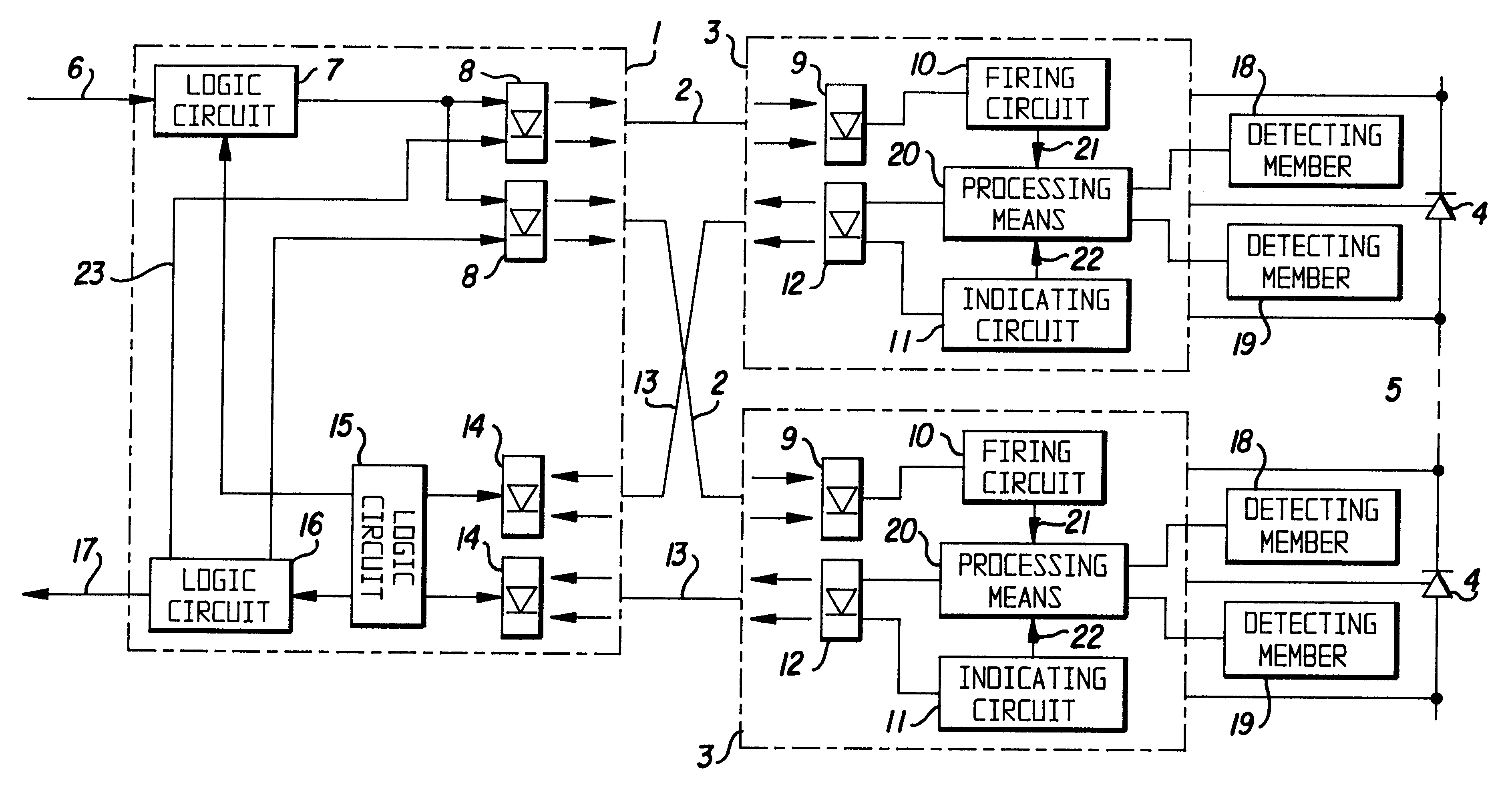
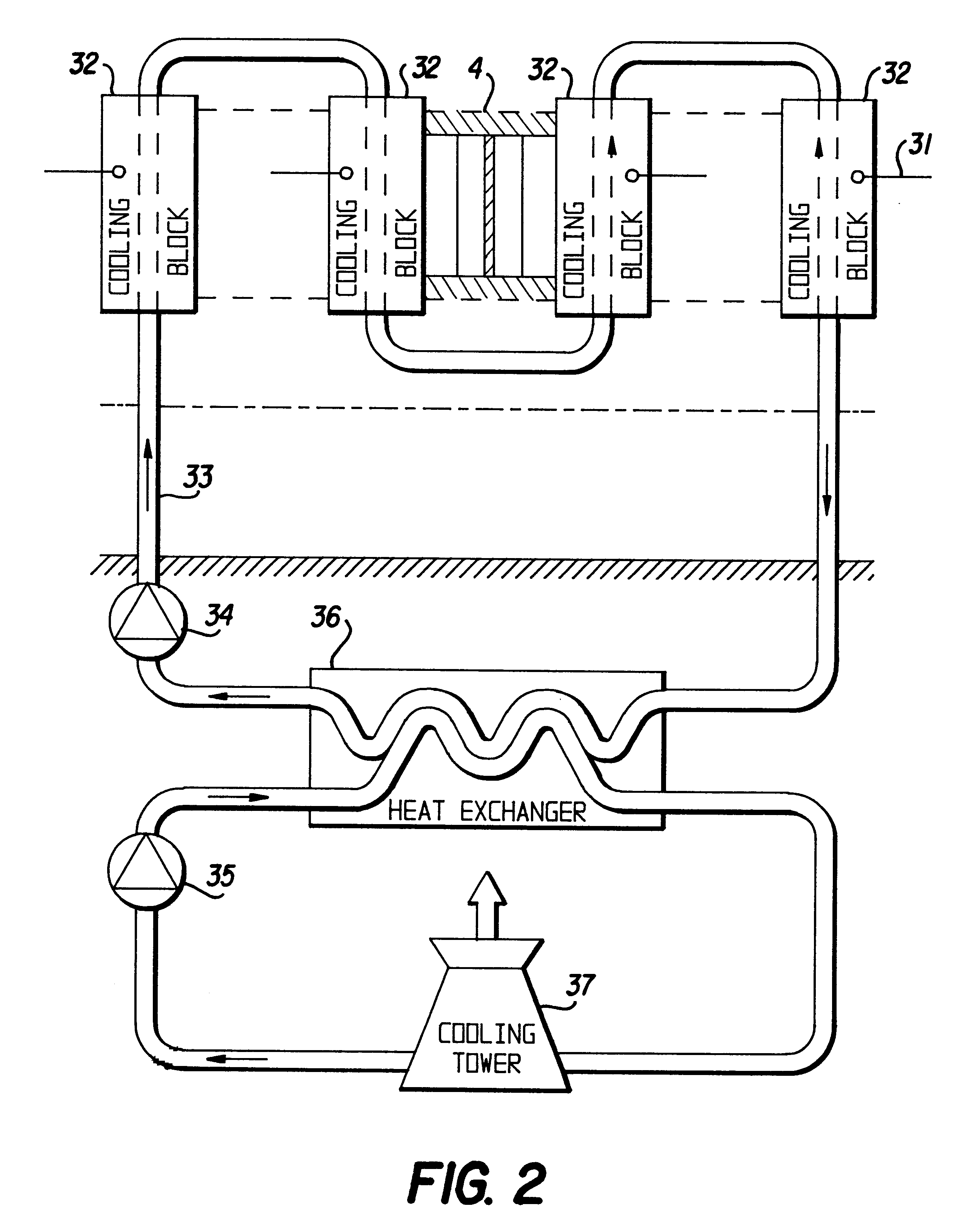
This object is according to the invention obtained by providing a device of the type defined in the introduction which comprises temperature detecting members arranged at at least some of said cooling blocks and adapted to send values detected thereby to the first control unit associated with the respective semiconductor component for elaborating and transmitting data with respect to the temperature of said cooling block to an arrangement for supervising the valve located on low potential level. By measuring the temperature at said different cooling blocks on high voltage potential level and directly close to the semiconductor components it will be possible to arrive to conclusions with respect to the temperature of the semiconductor components with a high reliability, which enables an elimination of a part of the protection systems for supervising cooling medium of high voltage converter stations already known or improving the accuracy thereof.
According to a preferred embodiment of the invention said temperature detecting members are arranged in each cooling block for detecting the temperature at each said semiconductor component of the valve. A temperature increase locally in any of the semiconductor components may by this efficiently be detected with a short delay, so that measures required, such as for example refiring of a semiconductor component not turned on or the like, may be carried out so as to reduce the power dissipation in the semiconductor component in question, disconnecting thereof or other measures may be taken before an over-current protection present will be activated. The state in the region of each individual semiconductor component of the valve may by this be efficiently supervised, so that possible deviations from the desired values of the temperature may be discovered early and suitable measures may rapidly be taken for minimising the number of drop-outs of the components, operation interruptions and the like. Thus, a fault or defect of a quite particular semiconductor component is here discovered in place, i.e. on high voltage potential level, without the problem that such information about such a fault is smeared out by the good function of a number of other such semiconductor components or by the distance between the high voltage potential level and the low potential level.

Problems solved by technology

However, the different said positions are located on high voltage potential level, which makes the supervision thereof difficult, so that the way of proceeding has until now with respect to most of the positions been restricted to carrying out a measurement of a parameter associated with the position in question on ground potential level so as to then calculate a probable value of the parameter on high voltage potential level.
It is natural that the accuracy will not be an optimum and that there are sources of faults making it possible to obtain values not at all corresponding to the reality.
Furthermore, the determination is very inaccurate, since for example a very increased temperature of a single semiconductor component may not be determined, since this high temperature will have a minor influence upon the temperature of the cooling liquid in said loop on ground potential level.

Method used


Image

  • HVDC power transmission system with cooling and switching device temperature detection
  • HVDC power transmission system with cooling and switching device temperature detection
  • HVDC power transmission system with cooling and switching device temperature detection

Examples


Embodiment Construction

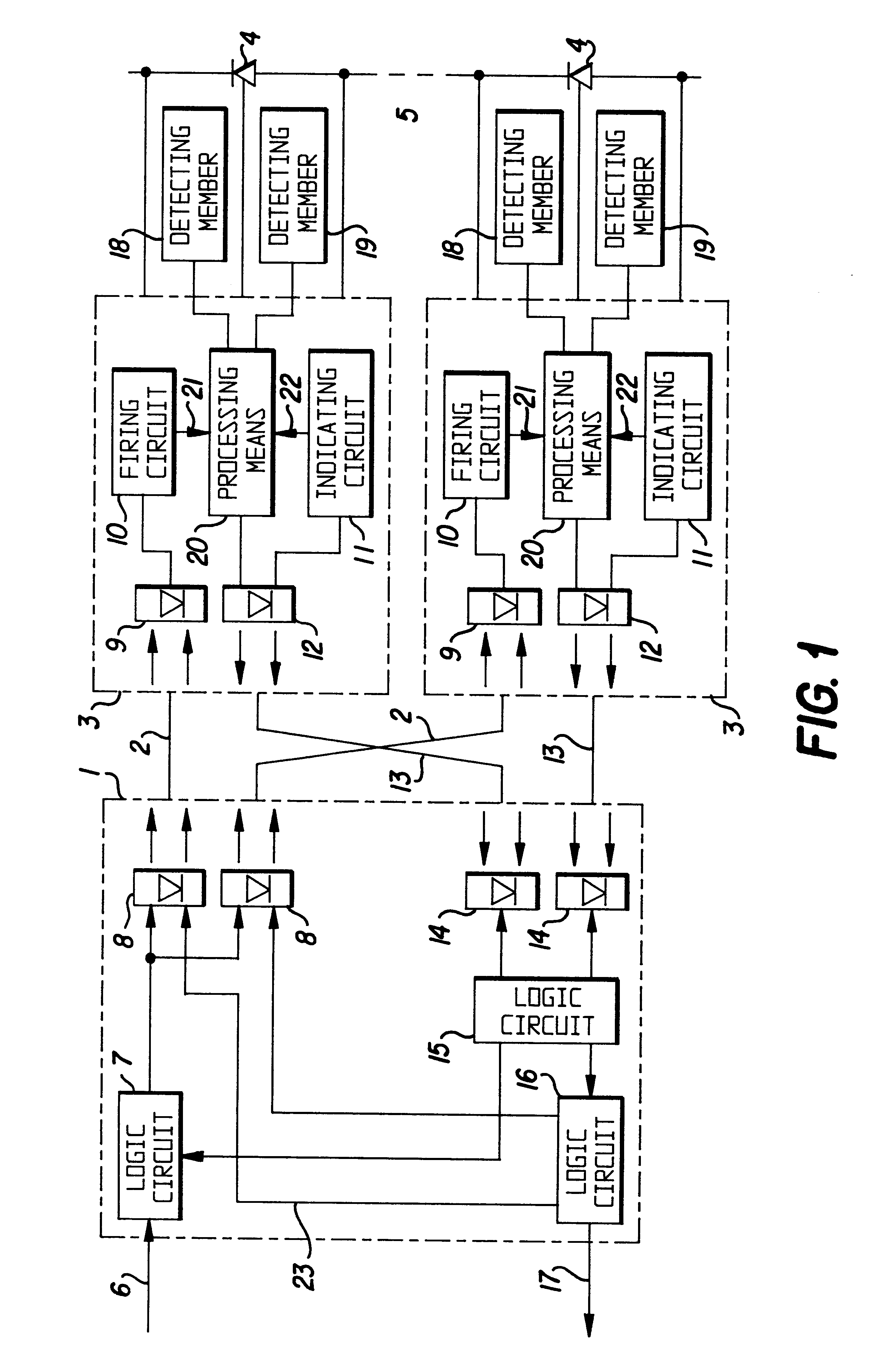
The general construction of a valve of a high voltage converter station, for example for converting High Voltage Direct Current (HVDC) into alternating current and conversely, and a valve control unit associated therewith, are schematically illustrated in FIG. 1, as well as schematically how the invention may be realised. A valve control unit 1 is in the converter station adapted to communicate through light conductors 2, i.e. opto-cables, with control units 3 for controlling semiconductor components 4 of turn-on-type belonging to the valve units, such as thyristors, in which the control then only relates to turn-on, and IGBTs, in which the control then also comprises turn-off. A greater number of such semiconductor components are usually connected in series within one single valve unit and intended to be controlled simultaneously through a control unit 3 each, which is indicated through the dashed line at 5. A valve consists in its turn of a plurality of such valve units. We will f...


PUM


Abstract

A device for supervising the cooling of a cooling system of a valve of a high voltage converter station located on high voltage potential level comprises members (31) located on high voltage potential level and adapted to detect the temperature at cooling blocks (32) of the valve on high voltage potential level and send values so detected to first control units (3) for controlling semiconductor components (4) of the valve. The first control units have means (20) for treating said values detected and the first control units are adapted to send data resulting from said treatment to an arrangement (16) for supervising said valve located on low potential level.

Description

FIELD OF THE INVENTION AND PRIOR ARTThe present invention relates to a device for supervising the cooling of a cooling system of a valve of a high voltage converter station located on high voltage potential level and having a plurality of valve units each having at least one semiconductor component of turn-on-type and for each semiconductor component a first control unit located on high voltage potential level and controlling said component, said first control units being connected to a valve control unit located on low potential level for communication between the valve control unit and the first control units, and said valve having an arrangement for cooling said semiconductor components with a cooling block associated with the respective semiconductor component and adapted to absorb heat from the semiconductor component and transfer it to a cooling medium.Such high voltage converter stations may for example be stations in plants for transmitting electric power through High Voltag...

Claims


Application Information

Patent Timeline
IPC IPC(8): H05K7/20
CPCH05K7/20927
Inventor ANG.STROM, URBANNYBERG, KRISTERSILJESTROM, ROLANDASPLUND, GUNNARBJORKLUND, HANS
Owner ABB (SCHWEIZ) AG
Learn More