Carburetor choke valve

a choke valve and carburetor technology, applied in the field of choke valves, can solve the problems of increased manufacturing cost, heavy overall weight of the choke valve 04 having a relief valve attached thereto, and inability to operate smoothly, etc., to achieve excellent relief function, reduce the number of components, and facilitate assembly

Inactive Publication Date: 2001-02-13
HONDA MOTOR CO LTD
View PDF10 Cites 12 Cited by
  • Summary
  • Abstract
  • Description
  • Claims
  • Application Information

AI Technical Summary

Benefits of technology

In view of the above described problems, the object of the present invention is to provide a choke valve with an excellent relief function, with

Problems solved by technology

Accordingly, the manufacturing cost is increased.
In addition, because of the large number of components, the overall weight of the choke valve 04 having a relief valve attached thereto is heavy.
If the choke valve 04 is

Method used


Image

  • Carburetor choke valve
  • Carburetor choke valve
  • Carburetor choke valve

Examples


Embodiment Construction

An embodiment of the present invention will now be described below with reference to FIGS. 1-10.

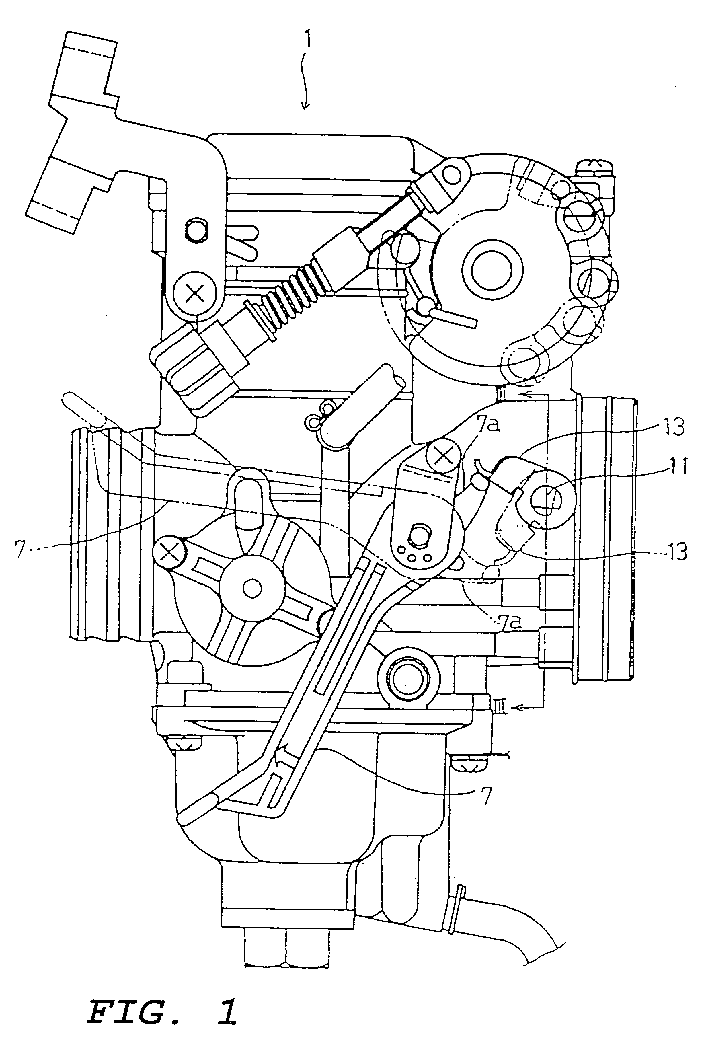
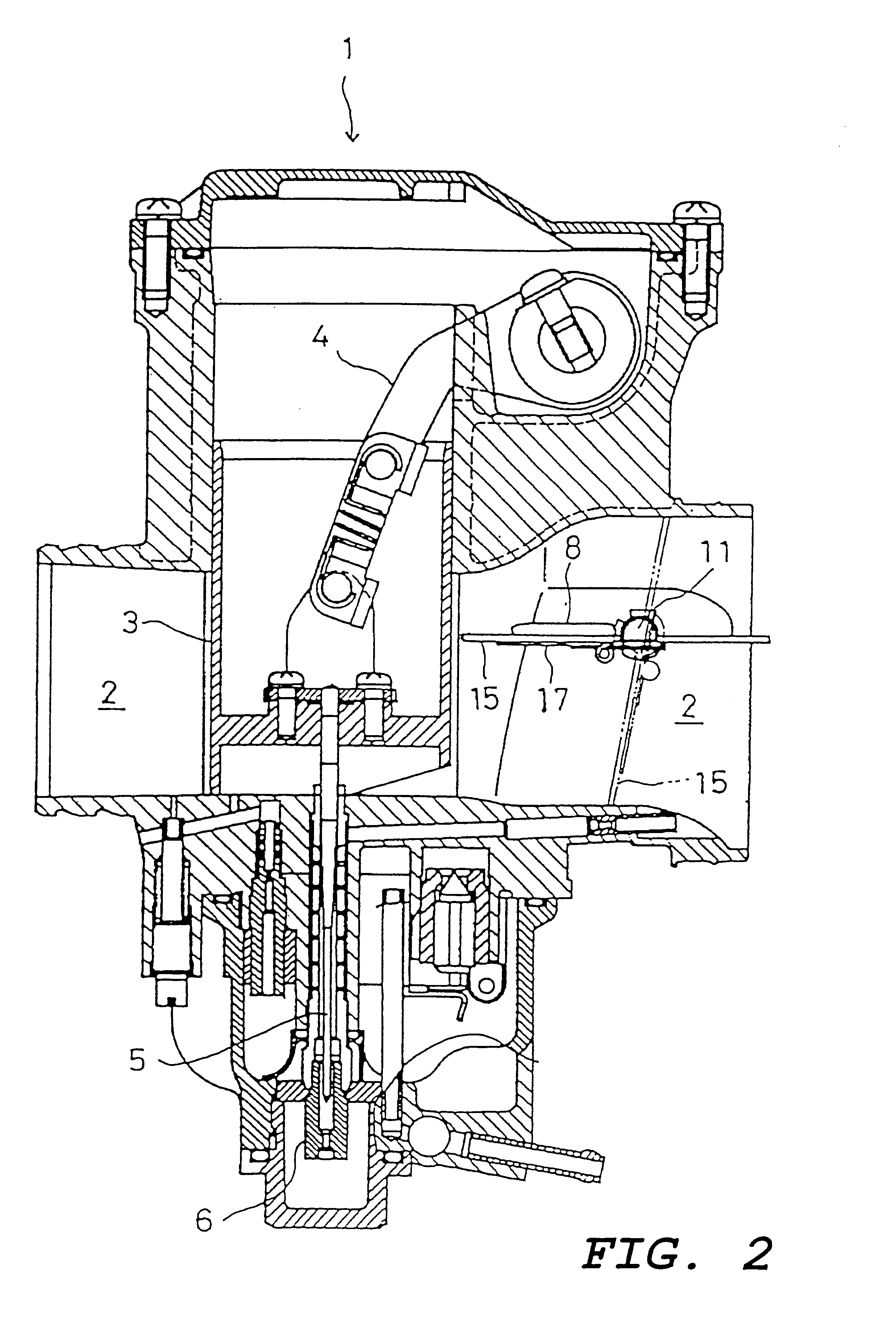
A side view of a carburetor 1 having a choke valve 10 of this embodiment is shown in FIG. 1, while a cross section is shown in FIG. 2.

The venturi surface is varied by raising a throttle valve 3 protruding into the inlet passageway 2 of the carburetor 1 using a throttle lever 4. Fuel is supplied from a main jet 6 into which a jet needle 5 protruding downward from the throttle valve 3 is inserted.

The choke valve 10 is provided in the inlet passageway 2 upstream of the throttle valve 3.

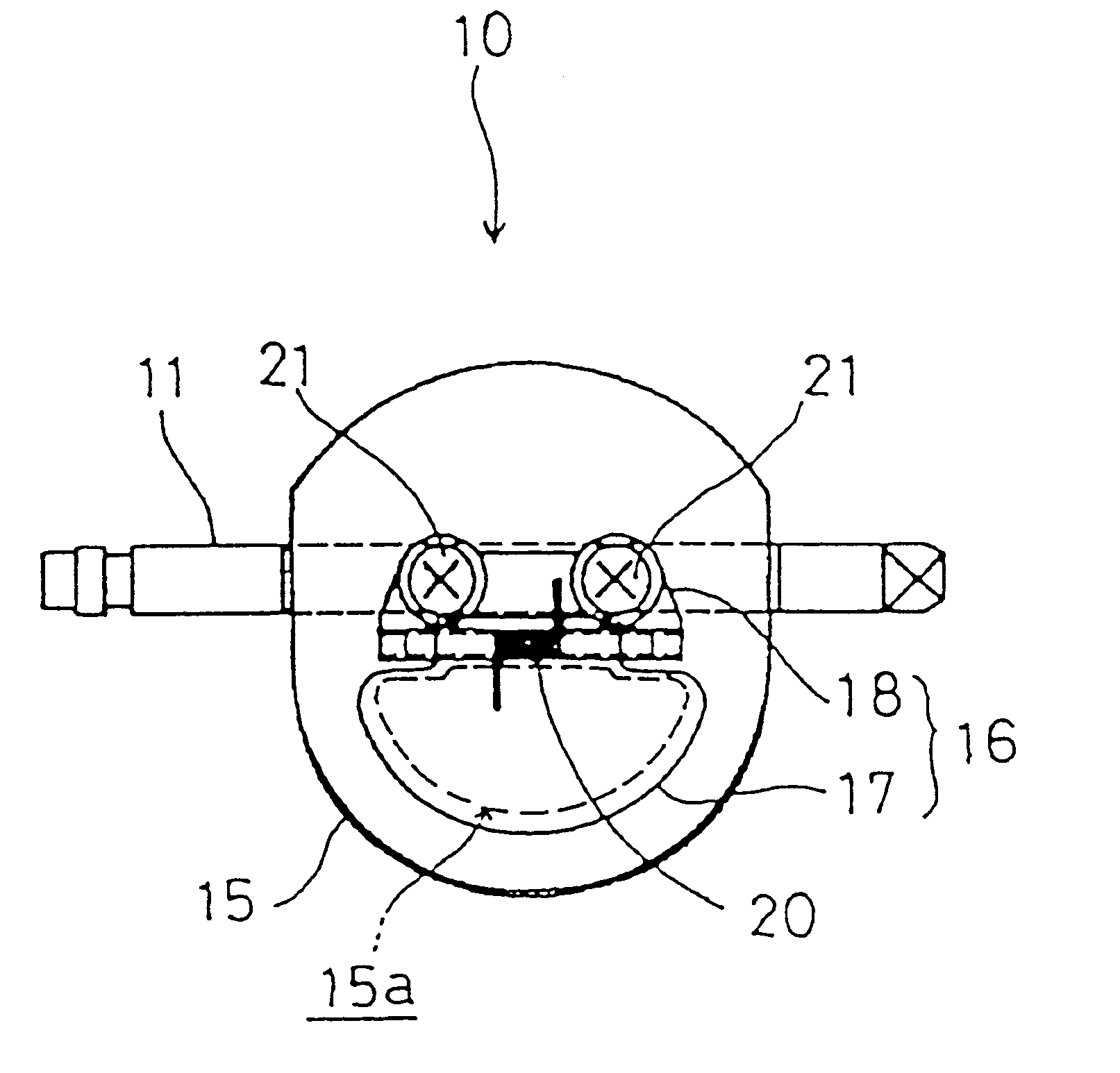
A pair of bearing boss sections 2a, 2a jut out in opposite directions from the upstream side inlet path 2 of the carburetor 1. A choke shaft 11 having both ends rotatably supported by the bearing boss sections 2a, 2a is constructed crossing the inlet passageway 2 (refer to FIG. 3).

As shown in FIG. 3, a torsion coil spring 12 is wound around inside the bearing boss section 2a at one end of the choke shaft, and ...


PUM


Abstract

To provide a lightweight choke valve that has a reduced number of components and is easy to assemble, despite being provided with a relief valve. A carburetor choke valve provided in an intake passageway of a carburetor includes a plate shaped choke valve body having a relief opening. A base end side of a plate shaped relief valve for opening and closing the relief opening is jointly fastened to a rotatably supported choke shaft crossing the intake passage of the carburetor.

Description

BACKGROUND OF THE INVENTION1. Field of the inventionThe present invention relates to a choke valve provided with a carburetor, and particularly to a choke valve provided with a relief valve in the choke valve body of the carburetor.2. Description of Related ArtA conventional example of such a choke valve provided with a relief valve is disclosed in Japanese Patent Laid-open No. Sho. 58-165555, and is shown in FIG. 14 of the present invention.A throttle valve 04 is arranged at a downstream side of a venturi section 03 in an intake passageway 02 of the carburetor body 01. A choke valve 05 is arranged at the upstream side of the venturi section 03.The choke valve 05 is attached with screws to a choke shaft 06 that is rotatably constructed in the intake passageway 02.A relief window 05a is formed through the choke valve 05. This relief window 05a opens and closes the relief valve 08.The relief valve 08 is formed as an elastic plate, and a base end part is attached to the choke valve 05 ...

Claims


Application Information

Patent Timeline
IPC IPC(8): F02M1/00F02M19/00F02M1/02F16K17/04
CPCF02M1/02F02M19/00
Inventor NOMURA, YOSHIMASA
Owner HONDA MOTOR CO LTD
Why Eureka
Try Eureka