
High temperature solid state hollow cylindrical battery including a plurality of solid polymer electrolyte cell

a rechargeable battery and solid polymer technology, applied in the direction of non-aqueous electrolyte cells, cell components, cell component details, etc., can solve the problems of inability to achieve high-temperature rechargeable batteries for liquid or gel electrolyte systems, inability to drill in the drilling environment, and relatively time-consuming replacement of batteries

Inactive Publication Date: 2001-02-13
HYDRO QUEBEC CORP +2
View PDF11 Cites 25 Cited by
  • Summary
  • Abstract
  • Description
  • Claims
  • Application Information

AI Technical Summary

Benefits of technology

According to another preferred embodiment, at least one safety vent is provided on at least one end cap, to permit purging of the battery system and escape of gases therefrom in case of undesirable pressure increase. This may be achieved by providing at least one vent opening in at least one end cap, and threaded means are provided to enable to screw the vent into the end cap.
According to the invention, the vent may include a rupture disc which is adapted to a maximum predetermined pressure to be maintained i...

Problems solved by technology

Although these batteries have excellent energy density (typically in the range of 900 Wh / L), the task of replacing them is relatively time consuming as compared to the usable life time of the batteries.
However, to Applicant's knowledge, high temperature rechargeable batteries for liquid or gel electrolyte systems are not presently available to achieve the above goal, unless they are provided with sufficient cooling device.
Of course this is not possible nor economical in a drilling environment.
A review of the prior art does not seem to provide an answer to the problems outlined above.
This battery does not provide an answer to the need of arranging a stack of batteries which are fixed relative to one another and operate together as a single battery container.

Method used


Image

  • High temperature solid state hollow cylindrical battery including a plurality of solid polymer electrolyte cell
  • High temperature solid state hollow cylindrical battery including a plurality of solid polymer electrolyte cell
  • High temperature solid state hollow cylindrical battery including a plurality of solid polymer electrolyte cell

Examples


Embodiment Construction

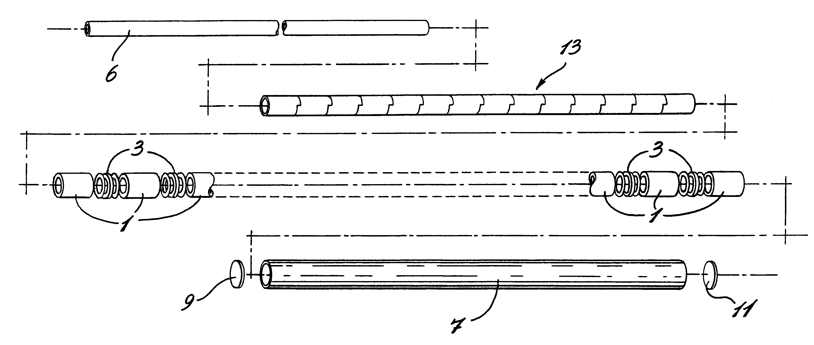
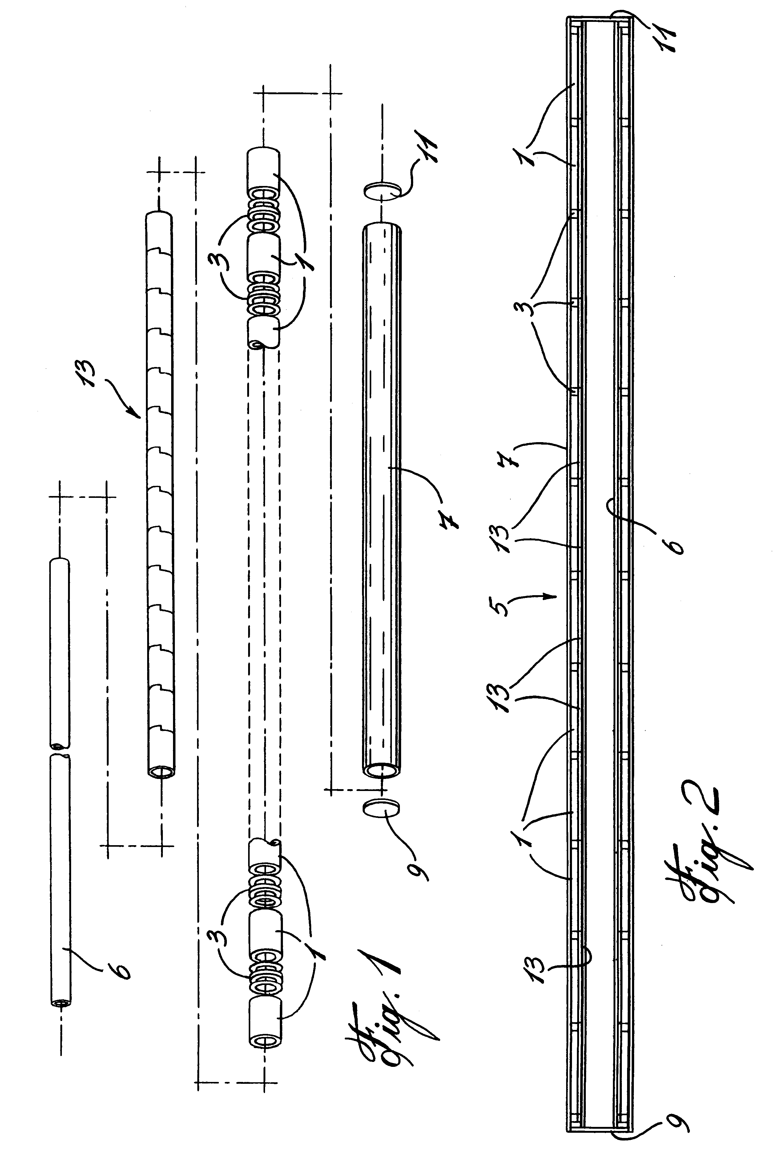
Referring to the drawings, it will generally be seen that the battery system illustrated in FIG. 1 is made of a plurality of battery units 1 all interconnected by means of interconnecting rings 3 as shown schematically in the exploded view of FIG. 1. The battery system 5 is illustrated in longitudinal cross-section in FIG. 2.

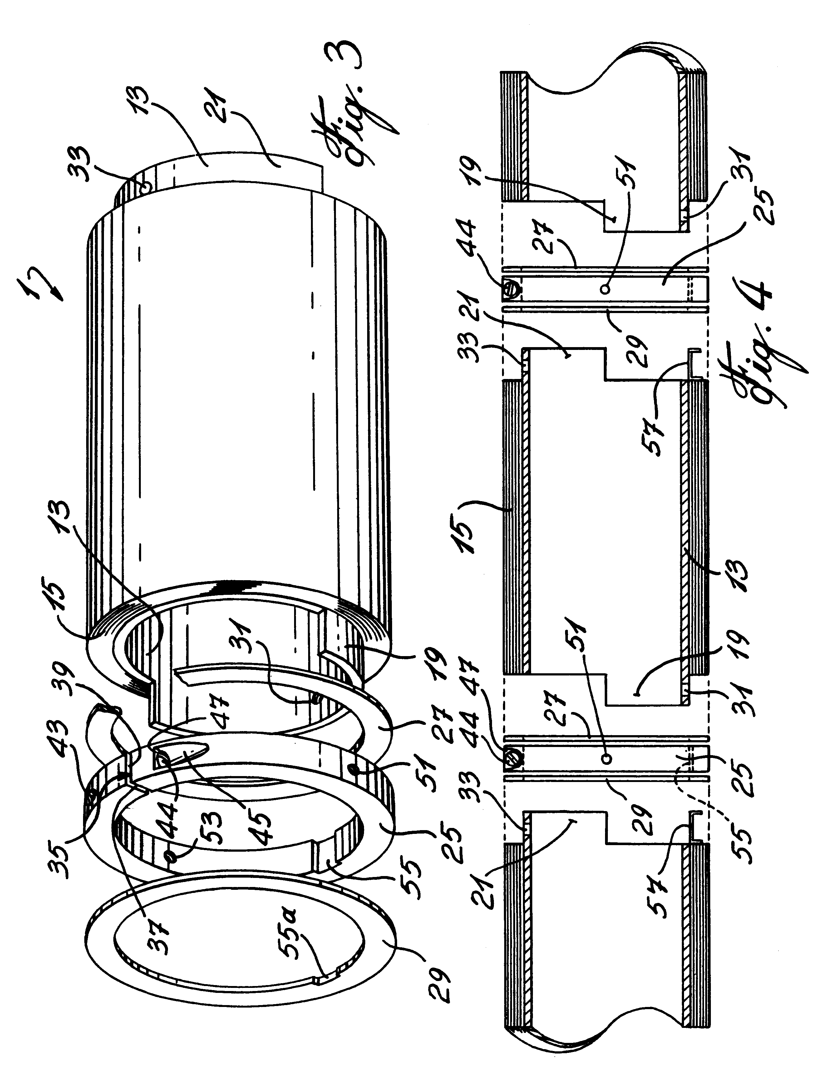
Referring to the drawings, more particularly FIGS. 2 and 5, it will be seen that the most prominent feature of battery system 5 according to the invention is the fact that a plurality of cells or battery units 1, here twelve in number, although this number can vary to a large extent, are connected in series while being mounted over inner tube 6 in one single battery containers, here outer tube 7. Battery system 5 is closed at both ends by means of hollow end caps 9, 11 (FIG. 2). Each cell 1 being hollow cylindrical or tubular as shown, more particularly in FIG. 3, once connected together as will be discussed in detail hereinafter, they form a continuous mandrel ...


PUM

PropertyMeasurementUnit
Temperatureaaaaaaaaaa
Pressureaaaaaaaaaa
Sizeaaaaaaaaaa

Abstract

There is disclosed a battery system to be used in downhole application. The battery system provides energy to operate the measurement devices associated with drilling. The system includes a plurality of cells, each comprising an electrically insulating mandrel which is shaped to fit over an inner tube, and a combination of an anode, a cathode and a solid polymer electrolyte, all disposed over the mandrel. The individual cells are mounted end to end and are interlocked together to prevent rotation of the cells relative to one another. The cells are electrically connected together and they are all mounted between an inner and an outer tube.

Description

BACKGROUND OF INVENTIONa) Field of the InventionThis invention relates to a high temperature solid state hollow cylindrical rechargeable battery. More particularly, the present invention is concerned with a high temperature rechargeable lithium battery system for downhole application, such as oil and gas well logging and drilling. Still more specifically, the present invention is directed to a battery system for well logging and drilling apparatuses which can be operated even at temperatures up to 125.degree. C. and higher for extended periods of time.b) Description of Prior ArtIn oil well logging and drilling operations, primary lithium batteries such as those based on a liquid thionyl chloride electrolyte have been used to power monitoring systems to collect information such as pressure, temperature, stress, magnetic field, and the like during the drilling operation. Although these batteries have excellent energy density (typically in the range of 900 Wh / L), the task of replacing ...

Claims


Application Information

Patent Timeline
IPC IPC(8): H01M2/02H01M10/36H01M10/40H01M6/44H01M6/42H01M6/18H01M10/052
CPCH01M2/025H01M6/181H01M6/44H01M10/052H01M50/138Y02E60/10
Inventor MARINCIC, NIKOLALETOURNEAU, CLAUDEHARRELL, JOHN W.
Owner HYDRO QUEBEC CORP
Learn More