Contact bridge arrangement for conductively interconnecting circuit boards

a technology of contact bridge and circuit board, which is applied in the direction of printed circuit aspects, coupling device connections, support structure mounting, etc., can solve the problems of increased cost of circuit board and overall electronic assembly, and inability to guarantee connection reliability

Inactive Publication Date: 2001-02-13
TELEFUNKEN PATENTVERWERTUN GMBH
View PDF17 Cites 22 Cited by
  • Summary
  • Abstract
  • Description
  • Claims
  • Application Information

AI Technical Summary

Problems solved by technology

First of all, the circuit boards and the overall electronic assembly are made significantly more expensive due to the additional costs of the plug connection and the connector cables wherever applicable.
Secondly, such connections are not very reliable, especially because each connection path can involve several independent connections in series, between the first circuit board and the first connector cable, between the first connector cable and the socket, between the socket and the plug, between the plug and a second connector cable, and between the second connector cable and the second c...

Method used


Image

  • Contact bridge arrangement for conductively interconnecting circuit boards
  • Contact bridge arrangement for conductively interconnecting circuit boards

Examples


Embodiment Construction

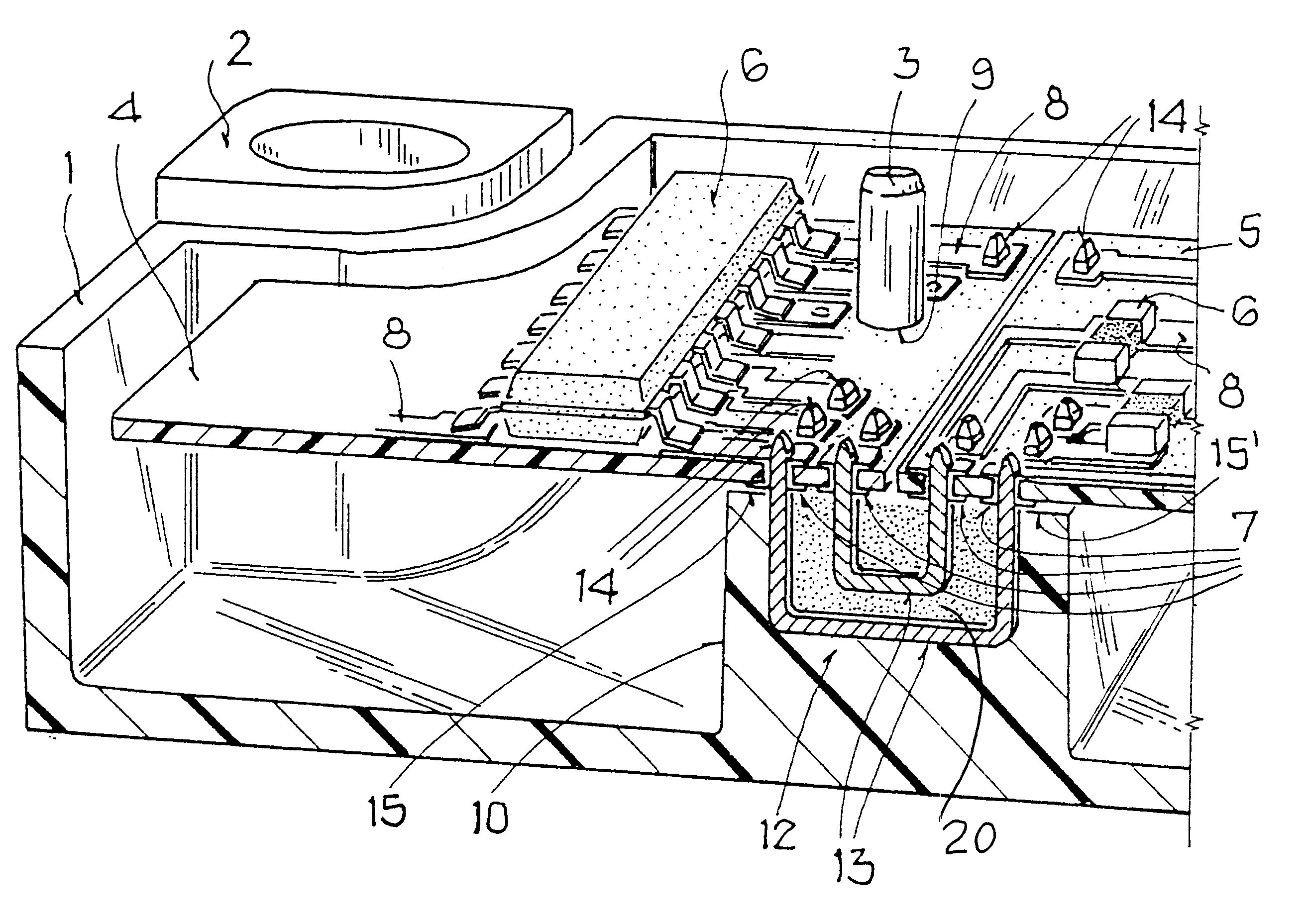
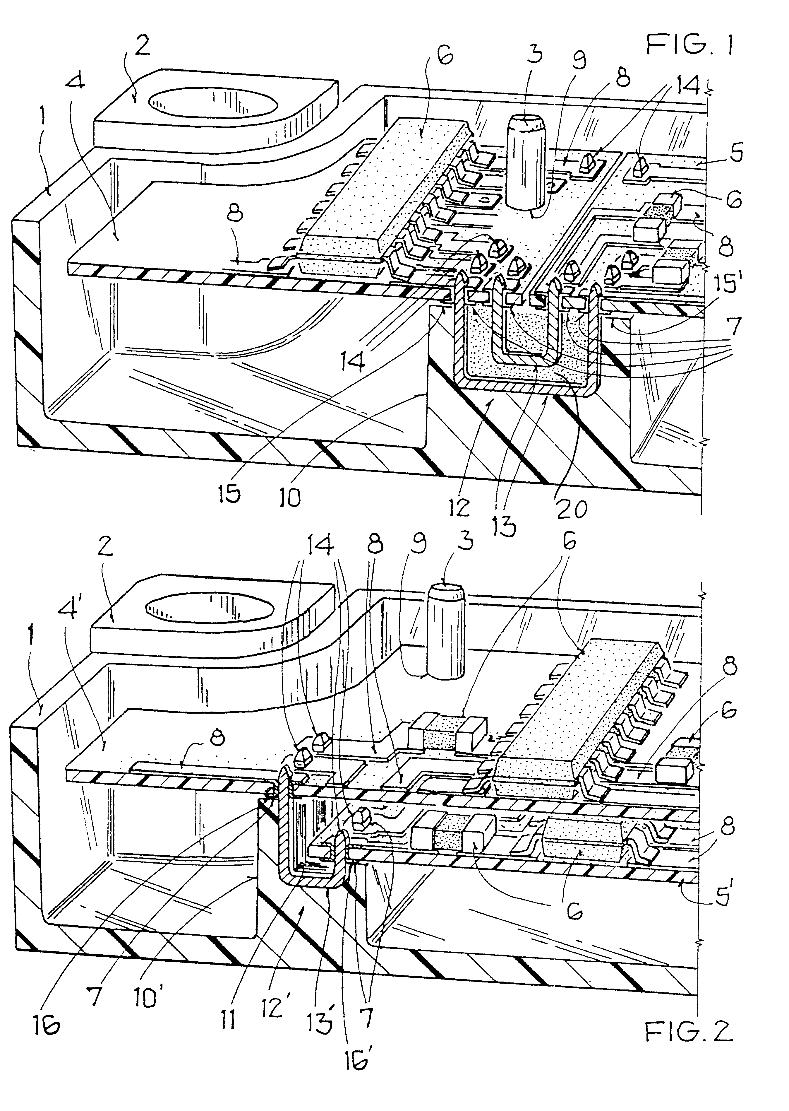
FIGS. 1 and 2 both show examples of the inventive contact bridge arrangement as used in an electronic assembly, such as an electronic control device like a triggering circuit module for an occupant safety system in a motor vehicle, for example. The electronic assembly or control device generally comprises a housing 1 made of plastic or the like, two circuit boards 4 and 5, or 4' and 5' arranged in the housing 1, and a contact bridge arrangement 10 or 10' provided in the housing.

The housing 1 includes a housing wall enclosing a housing cavity therein, and securing tabs or lugs 2 by which the housing 1 may be secured to the motor vehicle by means of screws, rivets or the like. The housing 1 may be closed and sealed by a cover plate in its final assembled condition, but such a cover plate is omitted from the drawings for purposes of clarity. The housing 1 further includes rod or pin-shaped mounting studs 3 on which the circuit boards 4, 4', 5, 5' are mounted; namely the studs 3 pass th...


PUM


Abstract

A contact bridge arrangement in a housing of an electronic assembly provides a simplified electrical interconnection of circuit boards while avoiding the need of electrical plugs, sockets and connector cables for connecting the circuit boards. The contact bridge includes an insulating block provided on the floor of the housing, and a plurality of conducting connectors embedded in the insulating block. First electrical contacts, such as contact pads with holes therein, are provided on the circuit boards, and engage the second electrical contacts in the form of contact pins provided by the free ends of the conducting connectors protruding from the insulating block. Assembling the arrangement simply requires pressing the circuit boards onto the contact pins of the contact bridge. The insulating block of the contact bridge may have a step configuration providing two offset flat support surfaces on which two circuit boards may be supported one above the other with a spacing therebetween.

Description

PRIORITY CLAIMThis application is based on and claims the priority under 35 U.S.C. .sctn.119 of German Patent Application 197 56 345.7, filed on Dec. 18, 1997, the entire disclosure of which is incorporated herein by reference.The invention relates to an arrangement for electrically contacting and conductively interconnecting at least two circuit boards arranged in a housing.BACKGROUND INFORMATIONConventionally, plug-in connections are used for electrically interconnecting different circuit boards that are typically arranged within a housing of an electronic assembly or module. Each such conventional plug-in connection is formed by a respective multi-conductor connector plug and a corresponding multi-conductor connector socket that are each respectively arranged on or connected to one of the circuit boards. In cases in which two circuit boards that are to be interconnected are in direct proximity to each other, it is commonplace to arrange the plug directly on one circuit board and ...

Claims


Application Information

Patent Timeline
IPC IPC(8): H05K3/36H05K1/14H05K3/34H01R12/04H01R12/52H05K5/02H05K7/14
CPCH05K1/142H05K3/368H05K7/142H01R12/52H05K1/144H05K3/3447H05K2201/09754H05K2201/0999H05K2201/2036H05K2203/167
Inventor FENDT, GUENTERBAUR, RICHARDBISCHOFF, MICHAEL
Owner TELEFUNKEN PATENTVERWERTUN GMBH
Why Eureka
Try Eureka