Accordingly, the gaseous medium of the dryer section has a temperature that is lower than the temperature on the outside of the partial circumference of the drying cylinder surrounded by the material web and the support band; and Because the temperature of the liquid or gaseous medium is lower than the temperature on the outside of the partial circumference of the drying cylinder surrounded by the material web and the support band, a great
discharge of liquid from the material web can be obtained. The support band and the side of the material web adjacent to the support band are cooled by the preferably
liquid medium such that a
temperature drop from the heated drying cylinder in the direction of the support band ensues. Both the
heat flow is increased and the discharge direction of the liquid leaving the material web partially as vapor is established thereby. Thus, the liquid preferably leaves the material web on the side adjacent to the support band. Due to the cooling of the support band by the medium, the liquid precipitates in the support band as condensate immediately after leaving the material web and is absorbed thereby. High drainage performance is achieved by the cooling of the support band and the material web, such that the drying performance of the dryer section can be increased while the structural length remains constant.
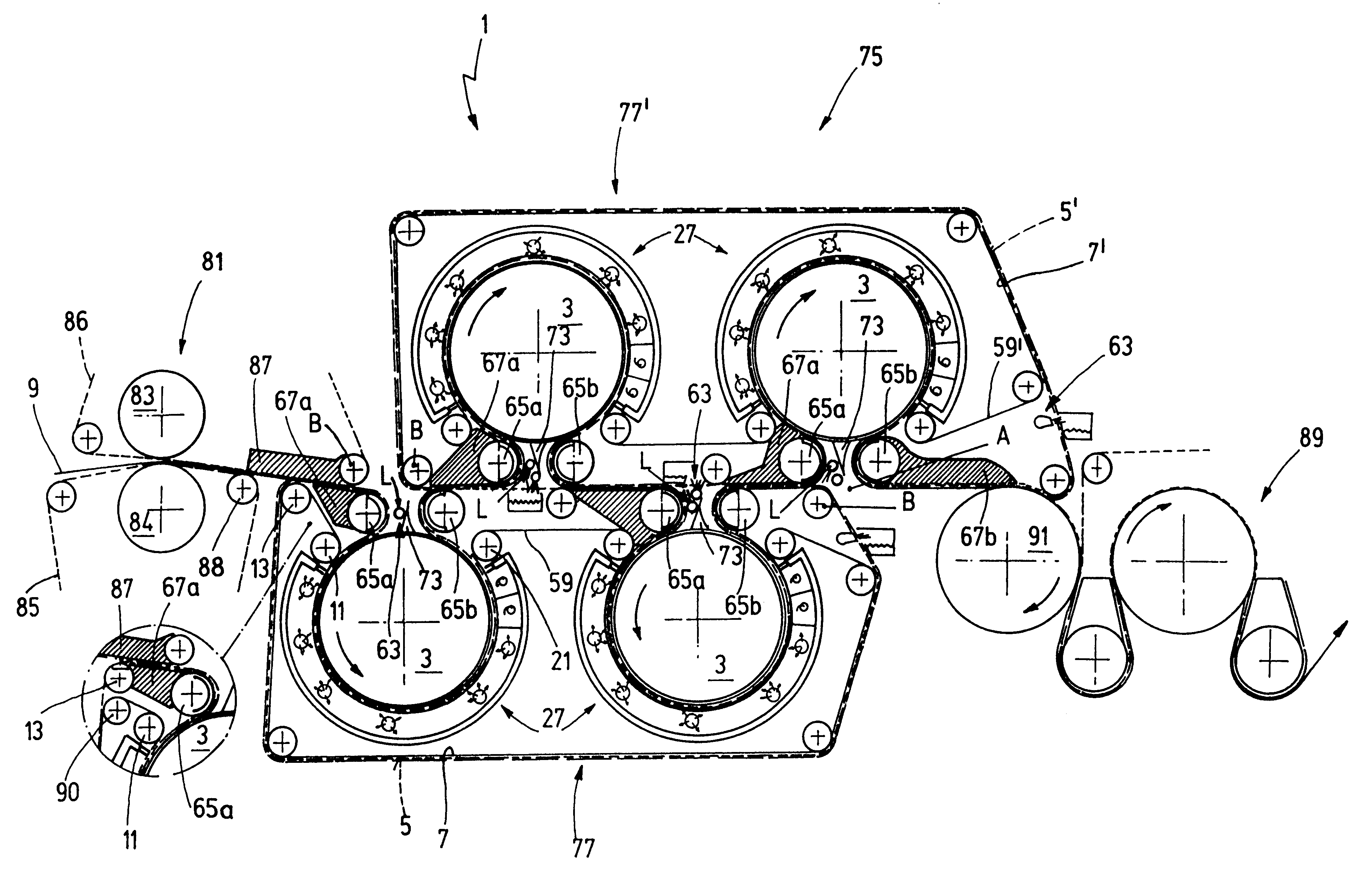
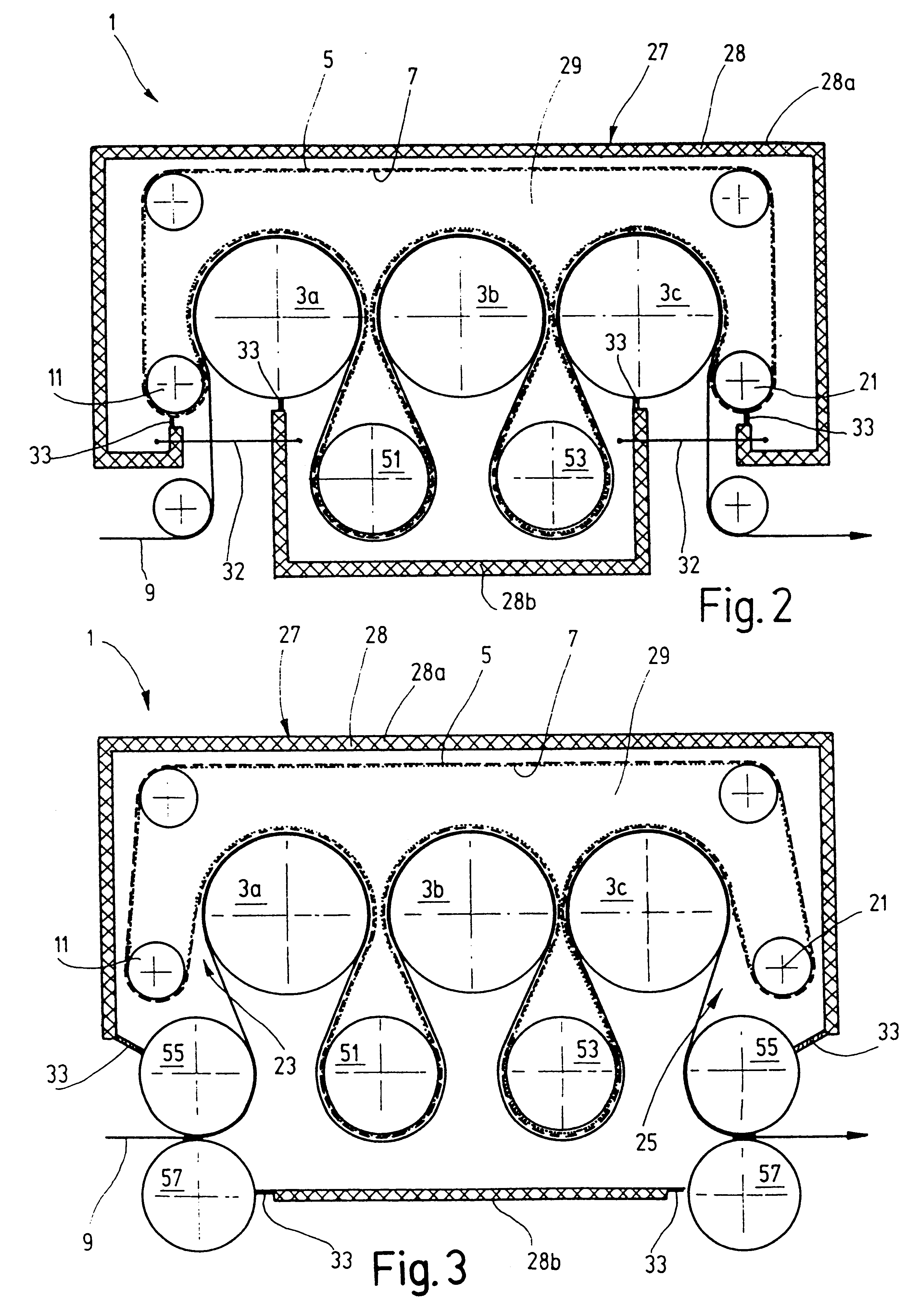
An exemplary embodiment of the dryer section in which at least one additional, second support band is guided on the outside around the drying cylinder is preferred. The second support band is thus guided such that the first support band is arranged between the material web and the second support band. Because the second support band is cooled directly by the pressurized medium, its temperature is lower than that of the first support band. In this way, and the liquid leaving the material web as vapor precipitates as condensate in the second support band. The vapor leaving the material web thus first penetrates the porous first support band and is absorbed by the second support band such that remoistening of the material web can be kept low. Obviously, it is also possible to guide more than two support bands, for example, three support bands, which are cooled by the gaseous medium, outside around the drying cylinder.
In an advantageous exemplary embodiment, provision is made for the second support band to have a coarser structure than the first support band. The support bands usually have a fabric-like structure. The fabric can have intertwined threads, for example, including multiple individual threads. In connection with the present invention, the term "structure" means the structure of the fabric, i.e., a support band with a coarse structure has larger intermediate spaces between the intertwined threads than a support band with a finer structure, whose threads are more densely intertwined. The first support band, adjacent to the material web, thus has a finer structure than the second support band, such that markings of the material web can be reliably avoided.
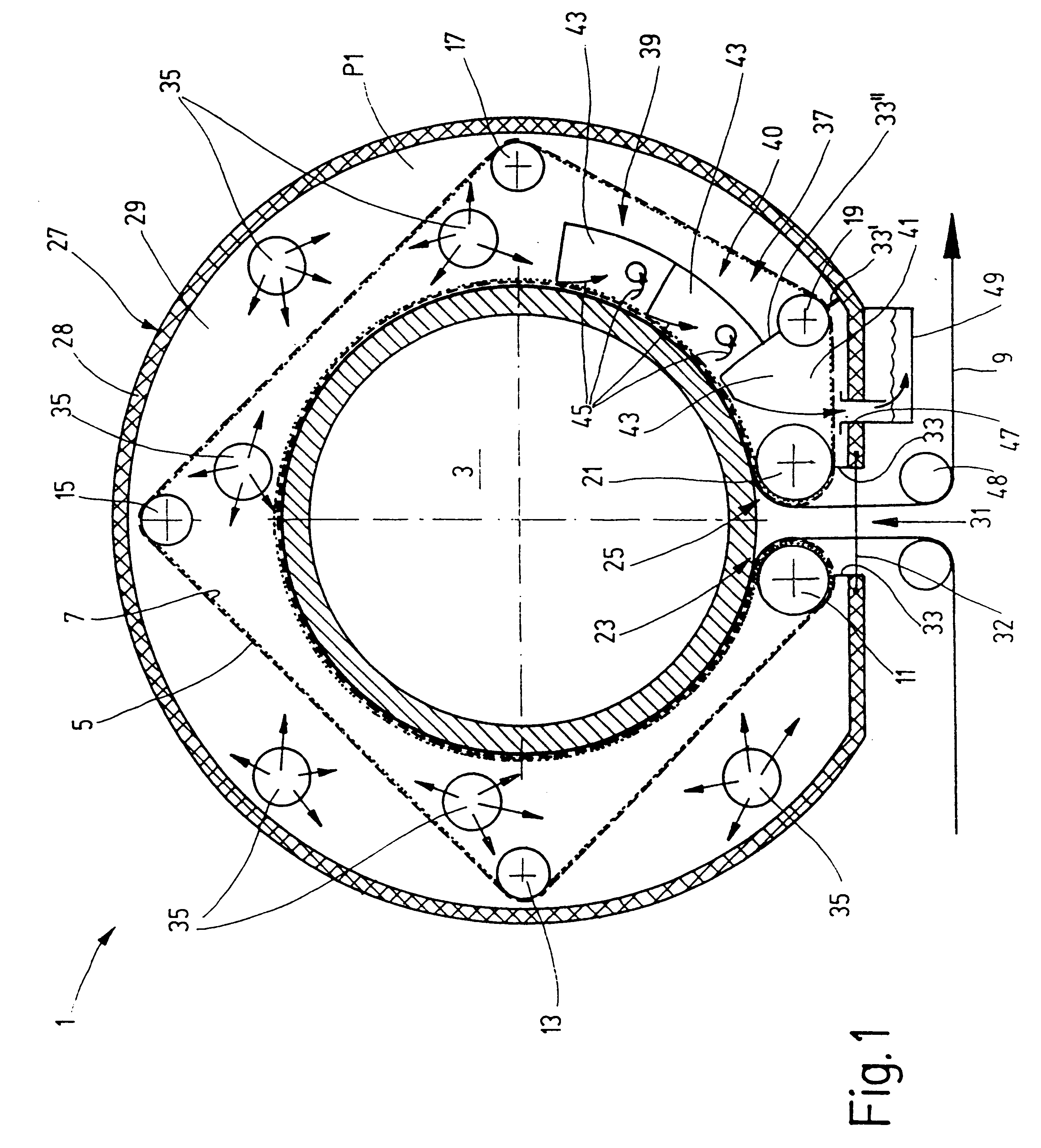
An exemplary embodiment of the dryer section distinguished by the fact that a medium-impermeable sealing band is guided on the outside around the drying cylinder is especially preferred. In connection with the present invention, the term "impermeable sealing band" means a liquid- and / or gas-impermeable band. At least one support band, which serves to absorb the liquid leaving the material web, is arranged between the sealing band and the material web. Because of the impermeability of the sealing band, the media pressure adjacent to the sealing band on the outside can be precisely transferred to the support band, without the medium being connected with the material web. The material web is pressed by it against the circumference of the drying cylinder, which results in an increased transfer of heat from the drying cylinder to the material web, which increases the
discharge rate of the liquid bound in the material web. Moreover, the material web is compacted by the media pressure such that its web properties are clearly improved. The pressure of the preferably
liquid medium, especially water, falls within a range from 0.001 bar to 12 bar absolute. The media pressure is preferably adjusted depending on the desired
heat output and / or the material web type and may also be higher than 12 bar, if appropriate.
Moreover, an embodiment of the dryer section in which the first support band, the second support band, and / or the sealing band is / are guided outside the pressure chamber of the overpressure cap between the discharge zone in which the band(s) run(s) off the drying cylinder and the intake zone in which the band(s) run(s) onto the drying cylinder is preferred. Thus, good
accessibility to the guide devices, such as guide rollers, over which the bands are guided, can be ensured. In addition, the structure of the overpressure cap can be simplified.
And finally, an exemplary embodiment of the dryer section is preferred in which the seals, for example, sealing strips, by which the pressure chamber of the overpressure cap can be sealed against the surroundings, work in coordination, with or without contact, with rollers which are pressed against at least one sealing band / support band or the material web or which are positioned at only a small distance therefrom. In an advantageous exemplary embodiment, provision is made that at least one seal works in coordination with the surface of a roller. Sealing thus occurs in a circumferential zone of the roller in which neither the material web nor a support band or sealing band is present. Thus, with a contact seal, i.e., when the seal touches the surface of the roller, wear of the bands and seals or damage to the material web can be avoided or kept low.

