
Fast ATA-compatible drive interface with error detection and/or error correction
a technology of error detection and error correction, which is applied in the direction of redundant data error correction, fault response, instruments, etc., can solve the problems of data bus bandwidth waste and bandwidth wasted
- Summary
- Abstract
- Description
- Claims
- Application Information
AI Technical Summary
Problems solved by technology
Method used
Image

Examples
Embodiment Construction
1. Error Detection--Full block transfers:
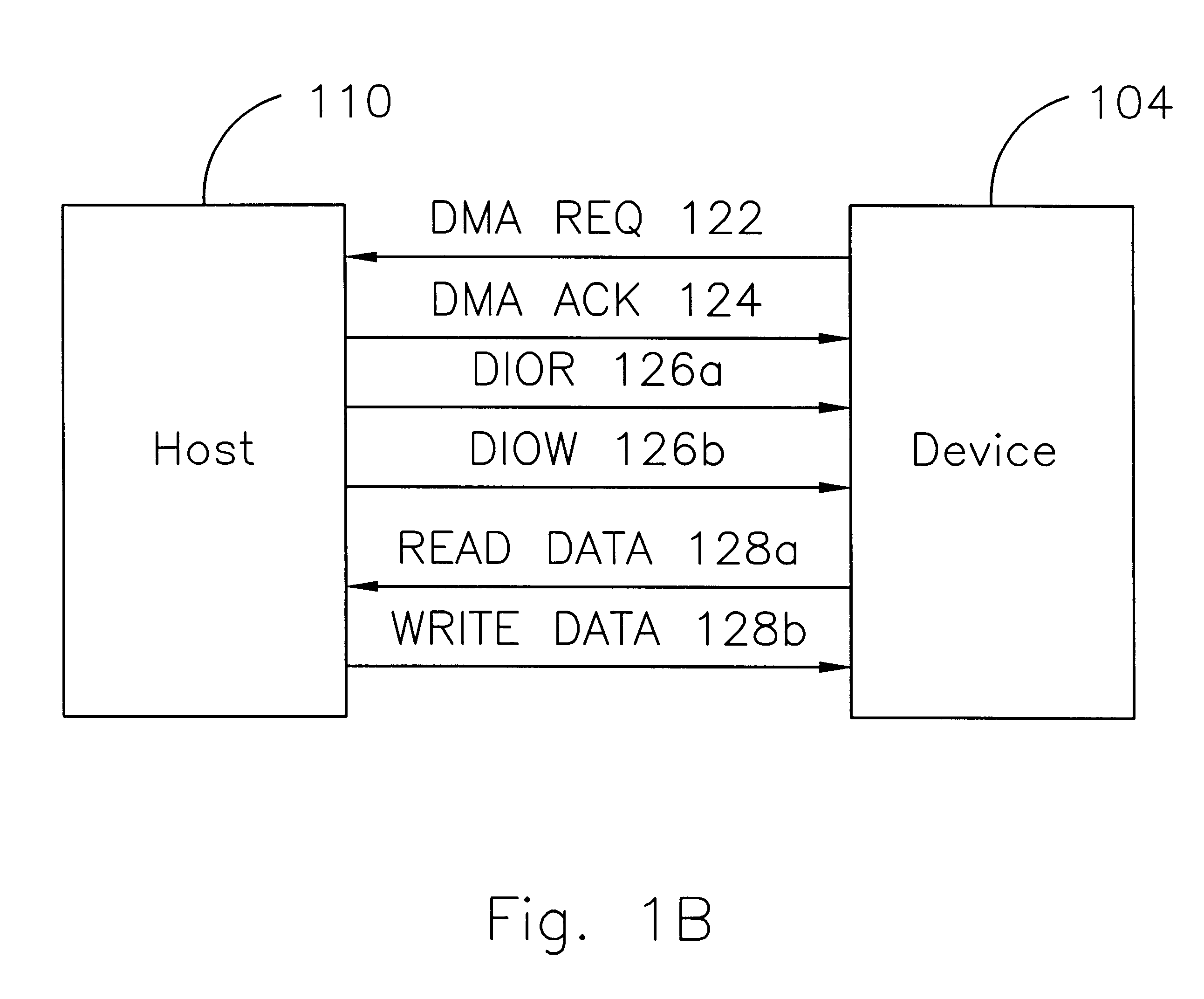
Referring to FIG. 4, there is shown the basic error detection method of the present invention. In this method, the sender accumulates each data word (e.g., Word.sub.-- 0, Word.sub.-- 1, etc.) placed on the bus into a send checksum word, and the receiver accumulates each word it receives from the data bus 103 into a receive checksum word. Immediately after the last (i.e., 256th) word is placed on the data lines 128 by the sender, the device 104 deasserts the DMA REQ signal on the DMA request line 122 and the last high to low transition of the DIOR-DIOW strobe on line 126 occurs, which triggers the receiver to input and internally accumulate the last data word in the data block being transferred. One significant change over the previously discussed protocol is that, after removing the last data word from the data lines 128, the sender places the final version of the send checksum (denoted as "parity" in FIG. 4) onto the data lines 128. The rece...
PUM
 Abstract
Description
Claims
Application Information