Hydrodynamic torque converter

a technology of torque converter and hydrodynamic force, which is applied in the direction of fluid gearing, coupling, belt/chain/gearing, etc., can solve the problems of rattling noise, development, and generation, and achieve the effects of reducing installation space, reducing noise, and improving sound quality

Inactive Publication Date: 2001-02-27
SCHAEFFLER TECH AG & CO KG
View PDF6 Cites 18 Cited by
  • Summary
  • Abstract
  • Description
  • Claims
  • Application Information

AI Technical Summary

Benefits of technology

An object of this invention is to provide a hydrodynamic torque converter with lockup clutch which exhibits acoustic characteristics superior to those of conventional torque converters, especially when the engin

Problems solved by technology

Rattling noises, which are generated by the engine-transmission unit when the vehicle is in use, de

Method used


Image

  • Hydrodynamic torque converter
  • Hydrodynamic torque converter
  • Hydrodynamic torque converter

Examples


Embodiment Construction

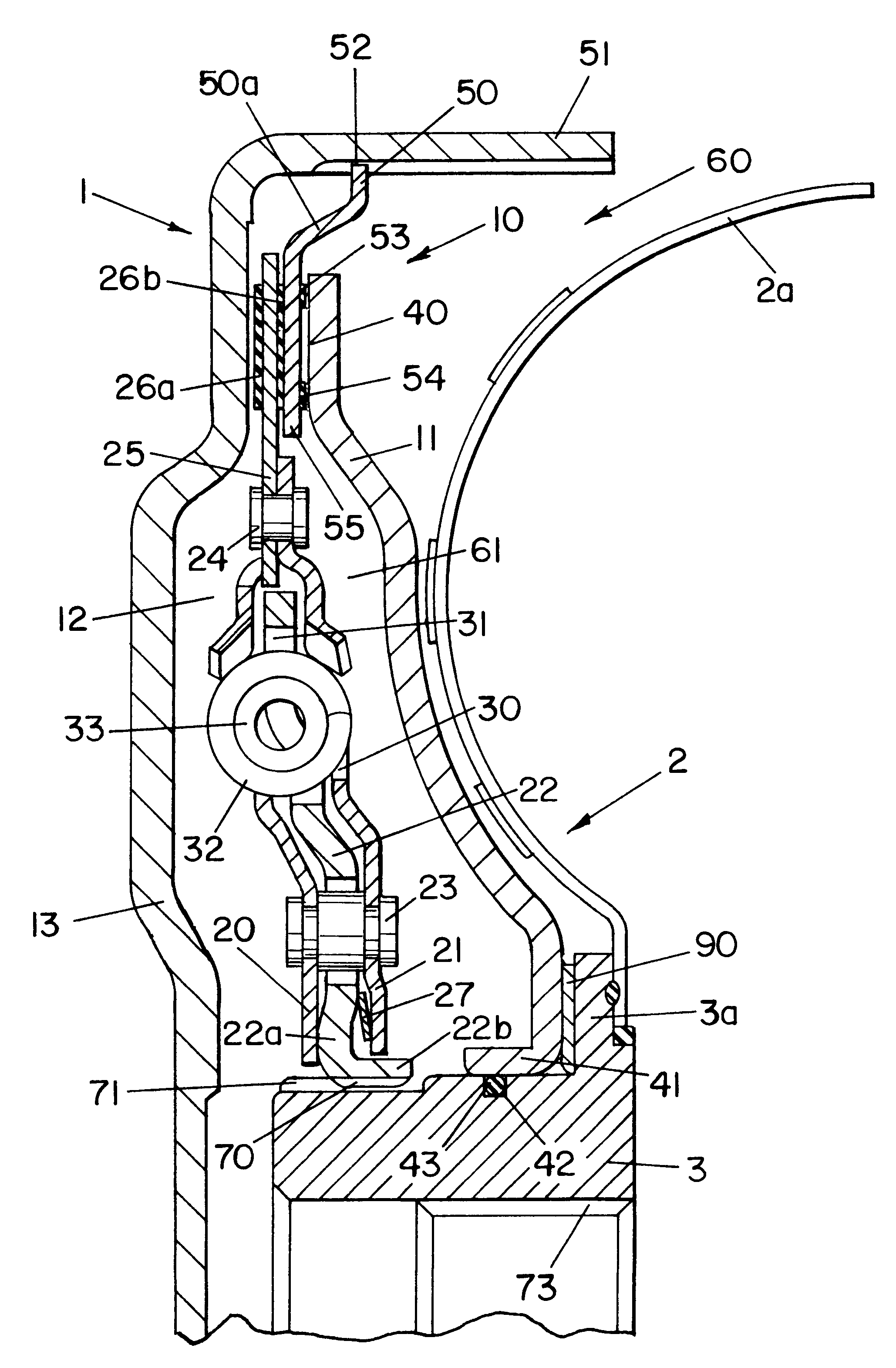
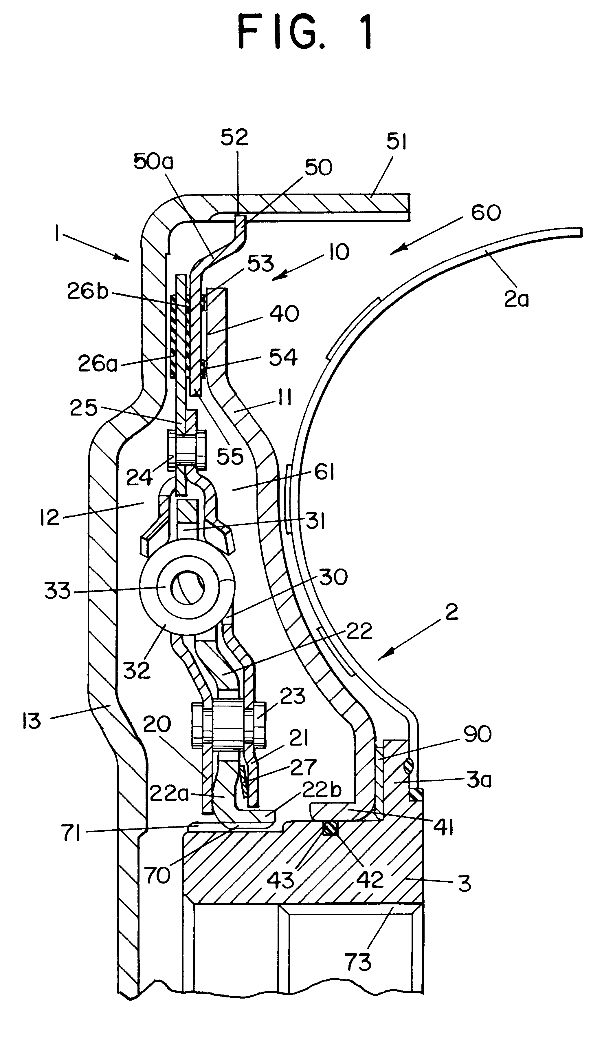
FIG. 1 shows a hydrodynamic torque converter 1 in which the turbine wheel 2 is indicated by a turbine wheel shell 2a. The turbine wheel / shell 2, 2a is non-rotatably mounted on or connected to a hub 3. The connection normally employs rivets or welds. In addition to the turbine wheel 2, the housing 13 of the torque converter 1 also receives a pump wheel and, if required, a stator.

The turbine wheel 2 of the torque converter 1 and the converter lockup clutch 10 with piston 11 and clutch disk 12 are installed within the housing 13. The clutch disk 12 comprises a torsional vibration damper located between its input and output sections.

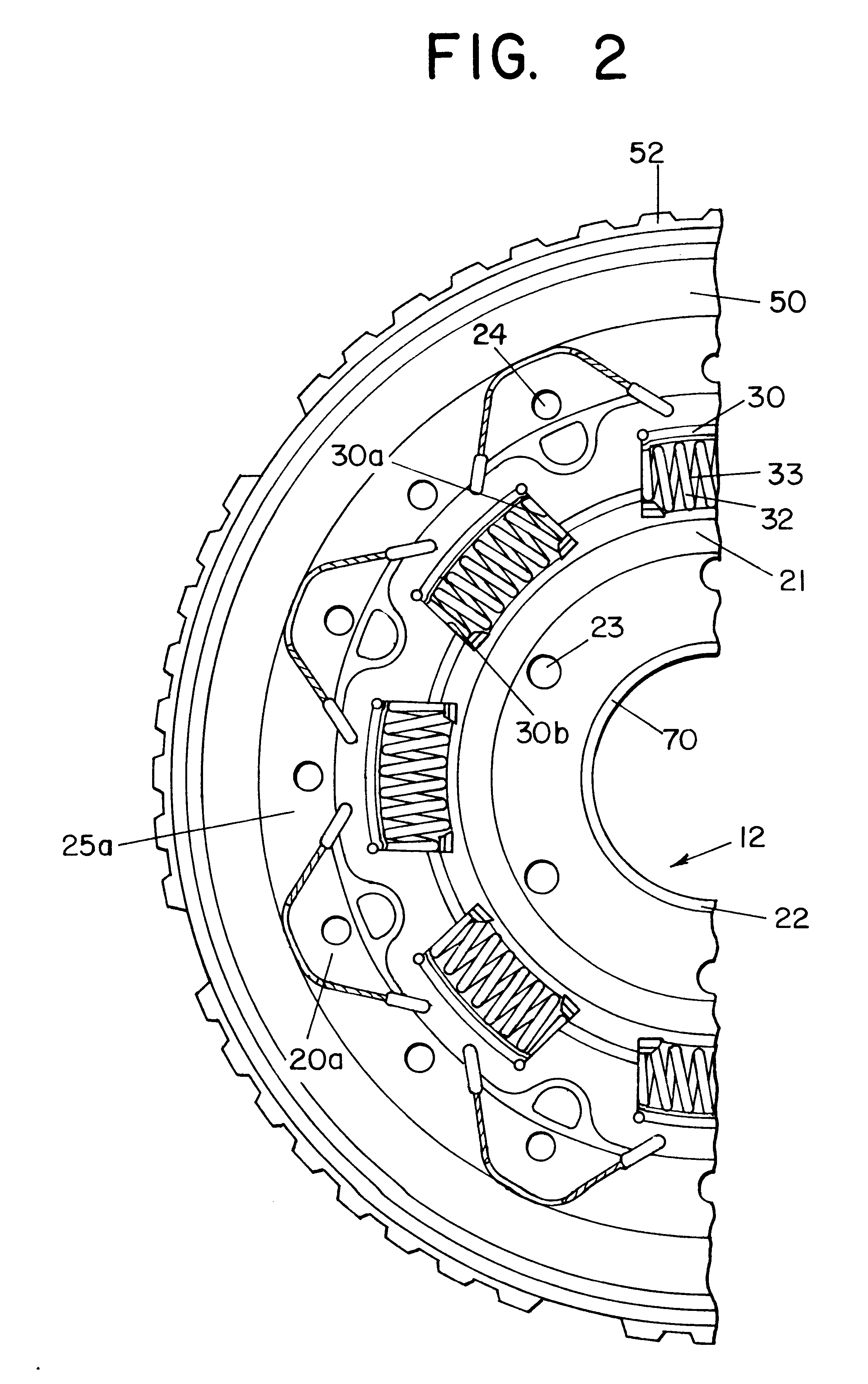
The clutch disk 12 consists essentially of a flange (output section) 22 mounted axially between two washers 20, 21 (input section). The washers are fixedly connected to each other at a fixed axial distance by at least one fastener 23 and / or 24, such as a rivet, so that they cannot turn relative to each other. A friction lining carrying plate 25 is connected ...


PUM


Abstract

A hydrodynamic torque converter wherein the housing is connected to the output element of an engine in the power train of a motor vehicle and receives a coaxial hub which is rotatable by the turbine wheel in the housing or by a clutch disk forming part of a lockup clutch and being axially movably but non-rotatably mounted on the hub. The lockup clutch further comprises a piston which is rotatably and axially movably mounted on the hub, and a laimina which is non-rotatably but axially movably mounted in the housing and extends radially inwardly between the piston and the clutch disk. The clutch is engaged when the piston is moved axially of the housing to thus urge the lamina against the clutch disk and to thus bias the clutch disk against an adjacent wall of the housing so that the clutch disc then transmits torque between the housing and the hub to thus bypass the torque transmitting connection between the housing and the hub by way of a satator wheel in the housing and the turbine wheel.

Description

The invention relates to a hydrodynamic torque converter with a turbine wheel and a converter lockup clutch accommodated in a housing, the converter lockup clutch having a piston which can be axially displaced on a hub, a clutch disk secured to the hub in such a way that it cannot rotate relative to the hub, and friction linings on the radially outer portion of the clutch disk. The radially outer part of the input section of the clutch disk is provided with friction linings, and the radially inner part of the output section of the clutch disk is connected to the hub by an internal gear.Within the housing, hydrodynamic torque converters of such type normally have a pump wheel connected to the housing in such a way that it cannot rotate relative to the housing, and a stator between the turbine wheel and the pump wheel. The piston is normally connected to the hub so that it cannot rotate or can be rotated relative to the hub within a predetermined damper angle range. Torque converters ...

Claims


Application Information

Patent Timeline
IPC IPC(8): F16H45/02F16H45/00
CPCF16H45/02F16H2045/0278F16H2045/0284F16H2045/0289
Inventor MIDDELMANN, VOLKERBOMAN, WENDYGRADU, MIRCEA
Owner SCHAEFFLER TECH AG & CO KG
Why Eureka
Try Eureka