Rotary engine and helicopter application

a technology of rotary engines and helicopters, applied in the field of rotary engines and helicopter applications, can solve the problems of unexpectedly low power ratio, and achieve the effect of low weight: power ratio and low weigh

Inactive Publication Date: 2001-02-27
KEEVER JAMES R
View PDF8 Cites 24 Cited by
  • Summary
  • Abstract
  • Description
  • Claims
  • Application Information

AI Technical Summary

Problems solved by technology

The disclosed design results in an even unexpectedly low weight: power ratio.

Method used


Image

  • Rotary engine and helicopter application
  • Rotary engine and helicopter application
  • Rotary engine and helicopter application

Examples


Embodiment Construction

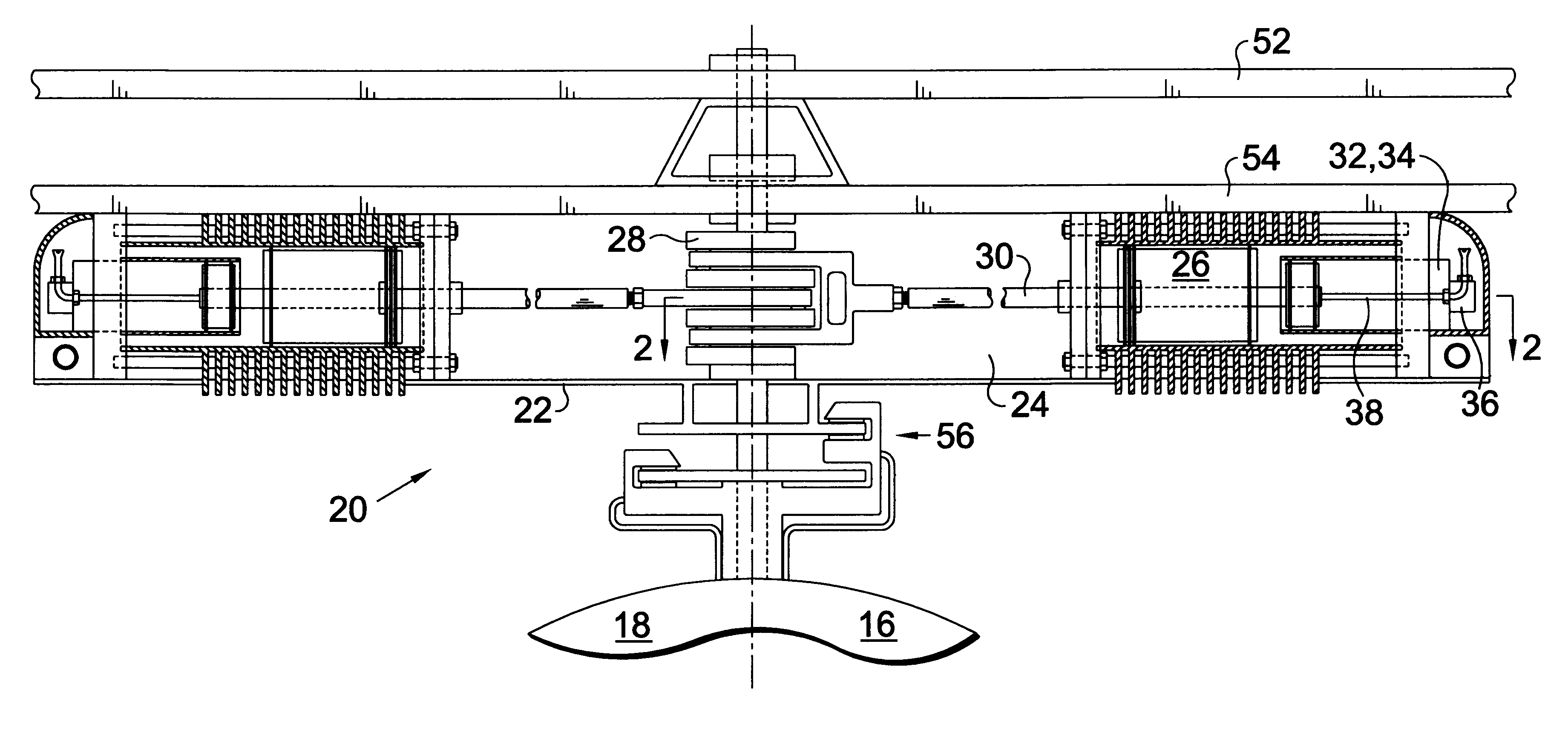
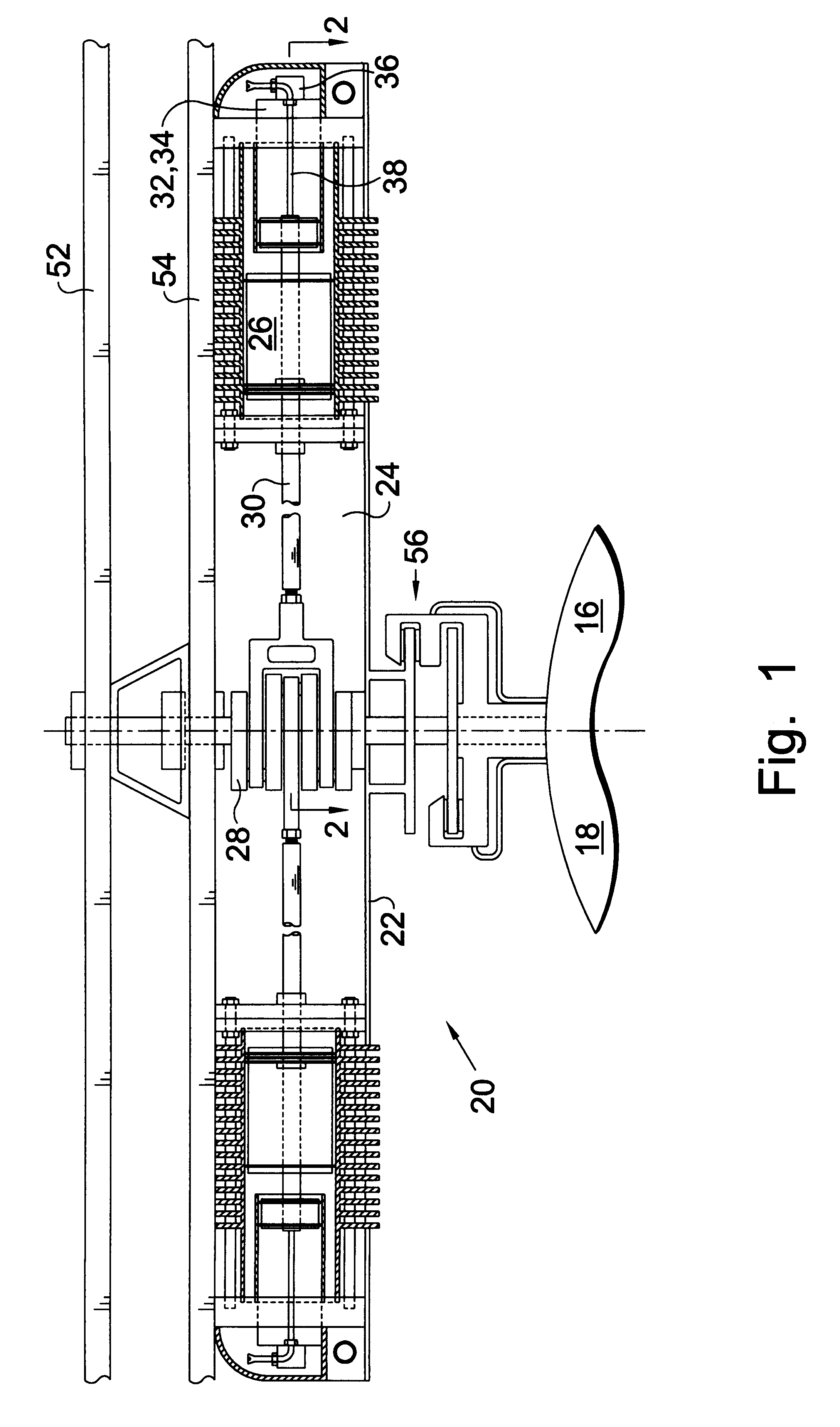
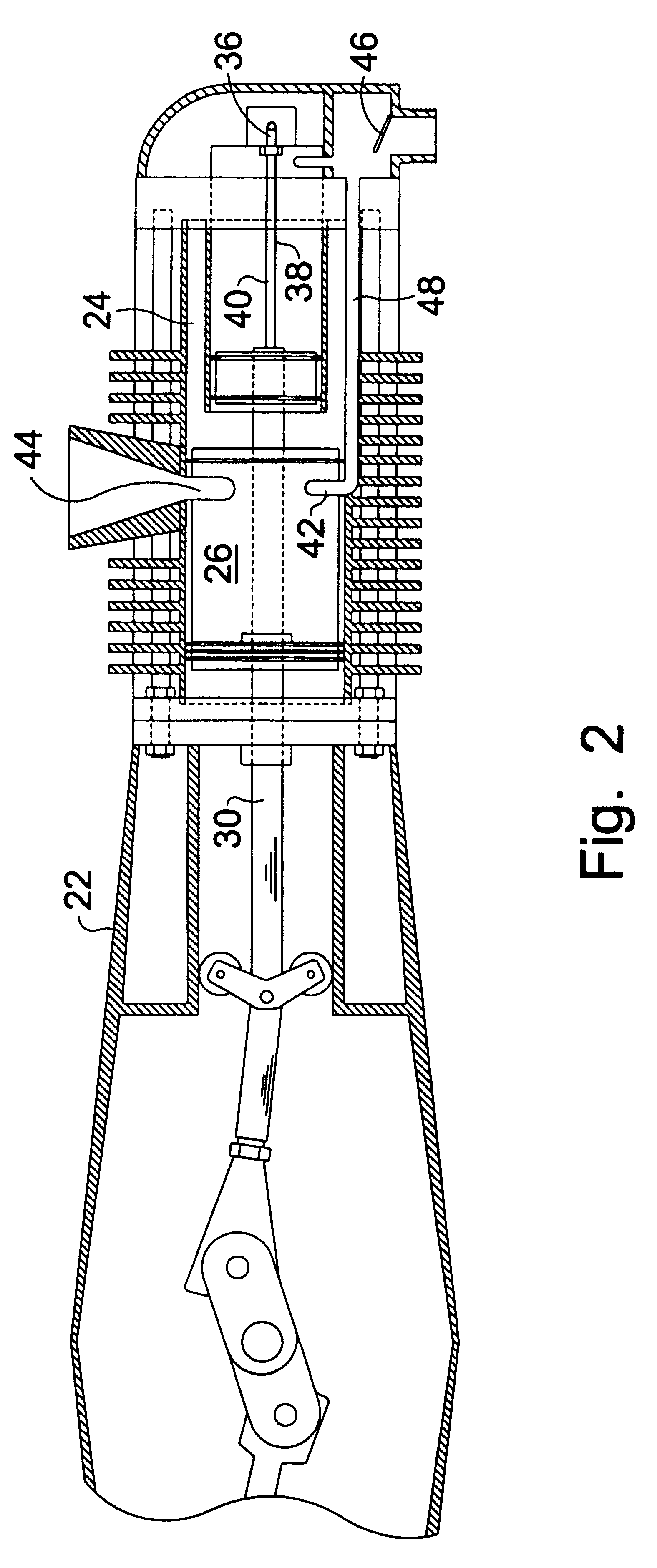
Turning now to the drawings and more particularly to FIG. 1 we have a cross sectional view of an improved rotary engine 20 mounted on a helicopter 18. The rotary engine 20 is of the type having a housing 22, cylinders 24 generally radially arranged within the housing 22, pistons 26 slidably positioned in the cylinders 24 defining combustion chambers 25 on an inner side portion of the pistons 26 slidably in the cylinders 24, a central crankshaft 28, reciprocating piston rods 30 having an inner end crankably connected to the crankshaft 28 and an outer end connected to the pistons 26. An oil reservoir 32 is positioned radially outwardly from the pistons 26 so that centrifugal force resulting from engine 20 rotation tends to keep oil 34 out of the cylinders 24.

An oil pump 36 is positioned in alignment with an axis through a cylinder 24. The pump 36 comprises a hollow rod 38 containing two opposite one way valves 40. The pump 36 lubricates the pistons 26 within the cylinders 24. In the m...


PUM


Abstract

In a rotary engine having rotating cylinders which burns a fuel which is not mixed with oil there is a real problem of centrifugal force form the rotating engine causing oil to flow into the combustion chambers. The disclosed rotary engine has oil reservoirs which are positioned radially outwardly from the pistons so that centrifugal force resulting from engine rotation tends to keep oil out of the combustion chambers. A helicopter utilising this rotary engine comprises: an aircraft body; a rotary engine having a housing containing an upright crankshaft which has a lower end portion rotatably attached above the aircraft body; a first main lifting rotor centrally attached to an opposite upper end portion of the crankshaft of the rotary engine; and, a second main lifting rotor attached to the housing of the rotary engine so that when the rotary engine is operating the first main lifting rotor is rotated in one direction, and the engine and the second main lifting rotor together tend to rotate in an opposite direction. A brake mechanism allows the relative rotational speed of the rotors may be controlled.

Description

This invention relates to radial engines in which the cylinders revolve about the crankshaft. More particularly this invention relates to an improved radial engine having an oil reservoir positioned radially outside a cylinder and having its intake fuel mixture compressed by the power stroke of a piston. This relatively powerful light weight engine is ideally suited for use in a helicopter having two rotors, each revolving in an opposite direction about a common axis.In a conventional rotary engine the oil reservoir is positioned between the rotating cylinders. Centrifugal force tends to draw the lubricating oil into the combustion chamber. This was the primary drawback of the French Ghome engine in the first world war. In addition to smoking, consumption of oil could cause engine failure. This ongoing problem of oil seepage has greatly limited the use of the relatively light weight rotary engine.In aviation particularly, there is a need great need for a reliable engine having a low...

Claims


Application Information

Patent Timeline
Patent Type & Authority Patents(United States)
IPC IPC(8): B64C27/10B64D27/04B64C27/12B64C27/04B64C27/00B64D27/00
CPCB64C27/10B64C27/12B64D27/04Y02T50/44Y02T50/40
Inventor KEEVER, JAMES R.
Owner KEEVER JAMES R
Why Eureka
Try Eureka