
Pivot spring automatic door sealing apparatus

a technology of automatic door sealing and pivoting springs, which is applied in the direction of sealing arrangements, construction, building components, etc., can solve the problems of prone to failure, sloppy apparatus, weak and easy to damage, and complex devices that are expensive to manufactur

Inactive Publication Date: 2001-03-06
SOWERS DAVID A
View PDF16 Cites 34 Cited by
  • Summary
  • Abstract
  • Description
  • Claims
  • Application Information

AI Technical Summary

Benefits of technology

It is another object of the present invention to provide such an apparatus which biases but does not force a sealing gate member toward a sealing position, so that an obstruction on the floor or threshold does not damage the apparatus.
It is still another object of the present invention to provide such an apparatus with a sealing gate member which cannot slide laterally during lowering and raising to minimize sliding and abrading contact with the threshold.
It is finally an object of the present invention to provide such an apparatus which is sturdy, simple and reliable in design, and relatively inexpensive to manufacture.
The apparatus preferably additionally includes a resilient sealing strip, and a groove is recessed into the lower surface of the gate member for retaining the resilient sealing strip to abut the threshold and obstruct passage of air. The groove and the resilient sealing strip are preferably of T-shaped cross-section to permit the sealing strip to slide axially into and out of the groove for periodic replacement and to prevent the sealing strip from sliding downwardly out of the groove.

Problems solved by technology

These devices have generally been complex and expensive to manufacture.
A problem with Beck is that the single holding point, free swinging sealing gate might rattle within the channel structure, making the door seem rickety.
Another problem is that the loose suspension of the sealing gate makes the apparatus sloppy, weak and prone to failure.
A problem with Berndt, Jr. is that the protruding end of the sealing member moves a pre-set, fixed distance when depressed and thus lowers the sealing member a constantly repeating fixed distance.
Should some object obstruct the lowering of the sealing member, the closing of the door could damage the apparatus.
Another problem is that the sealing member moves laterally as well as downwardly, making abrading sliding contact with the floor.
Despite this adjustability, the unexpected presence of an object below the door could cause damage, as indicated above for Berndt, Jr.
Ohi is also relatively complex and expensive to manufacture.
A problem with Hawk is that the pivoting sealing strip structure is relatively delicate, and it could be damaged by abrupt contact with an obstacle in the path of the door.
Another problem is that the downwardly protruding rods might touch and scratch the floor as the door swings.

Method used


Image

  • Pivot spring automatic door sealing apparatus
  • Pivot spring automatic door sealing apparatus
  • Pivot spring automatic door sealing apparatus

Examples


Embodiment Construction

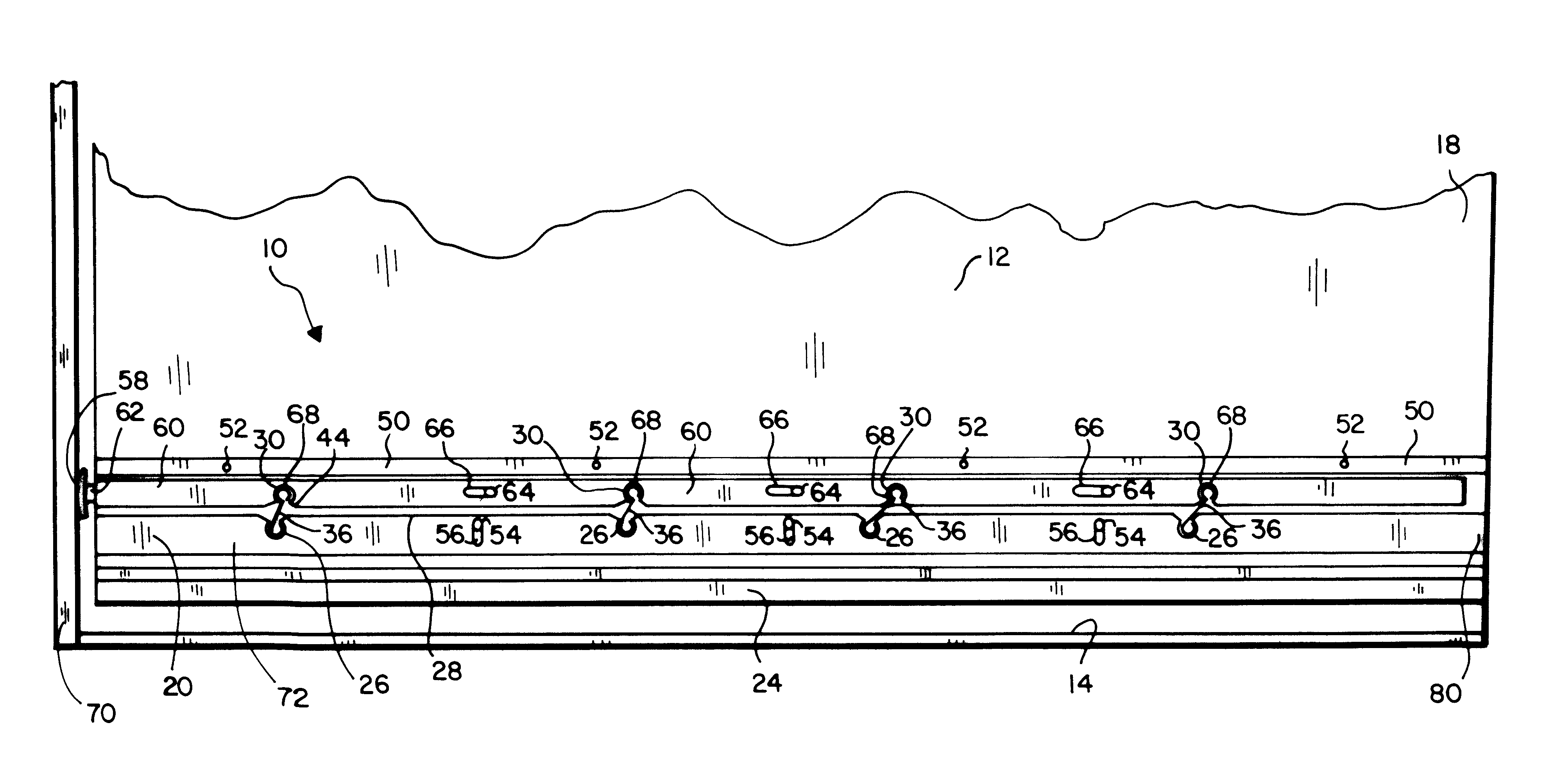
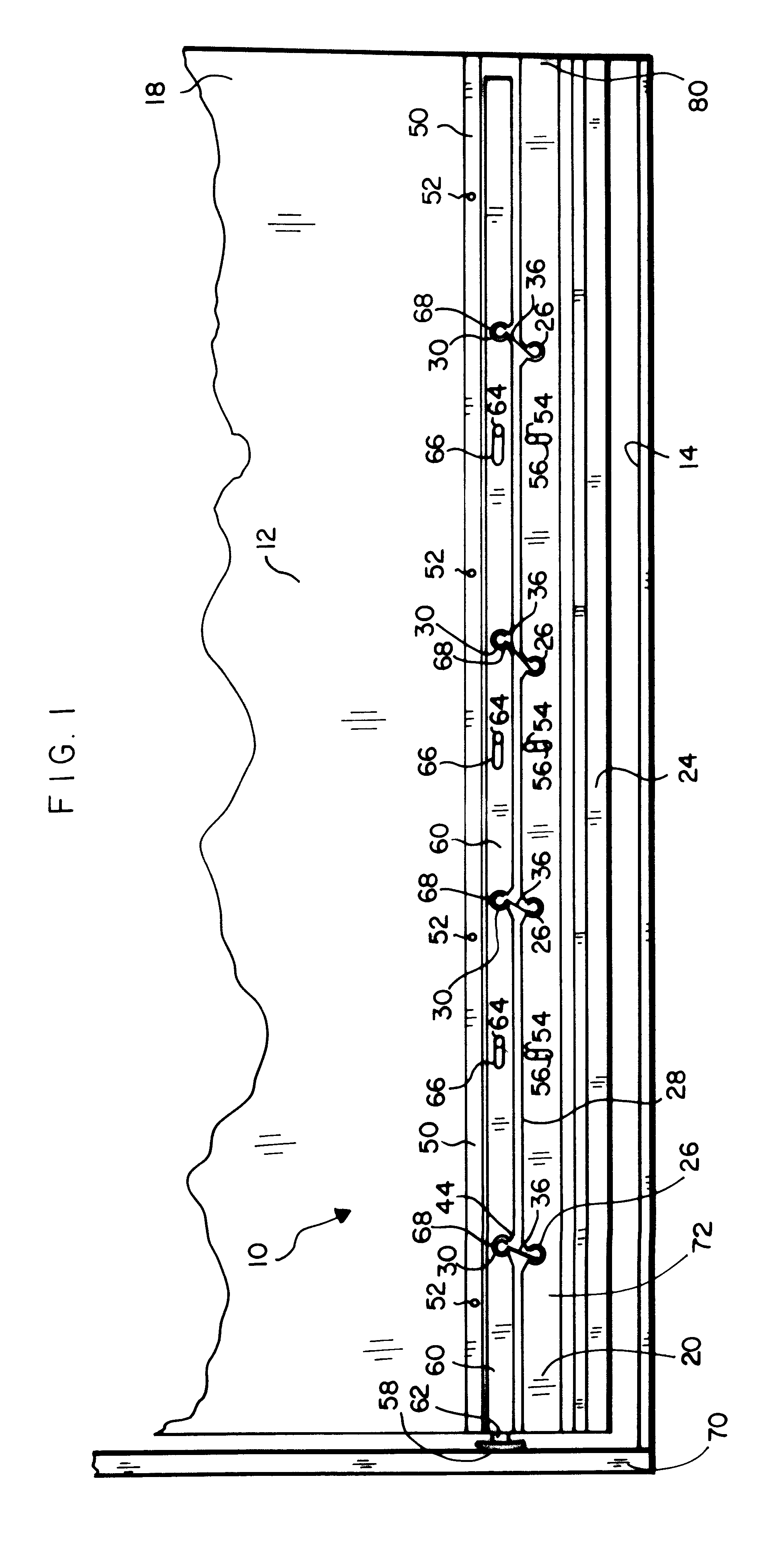
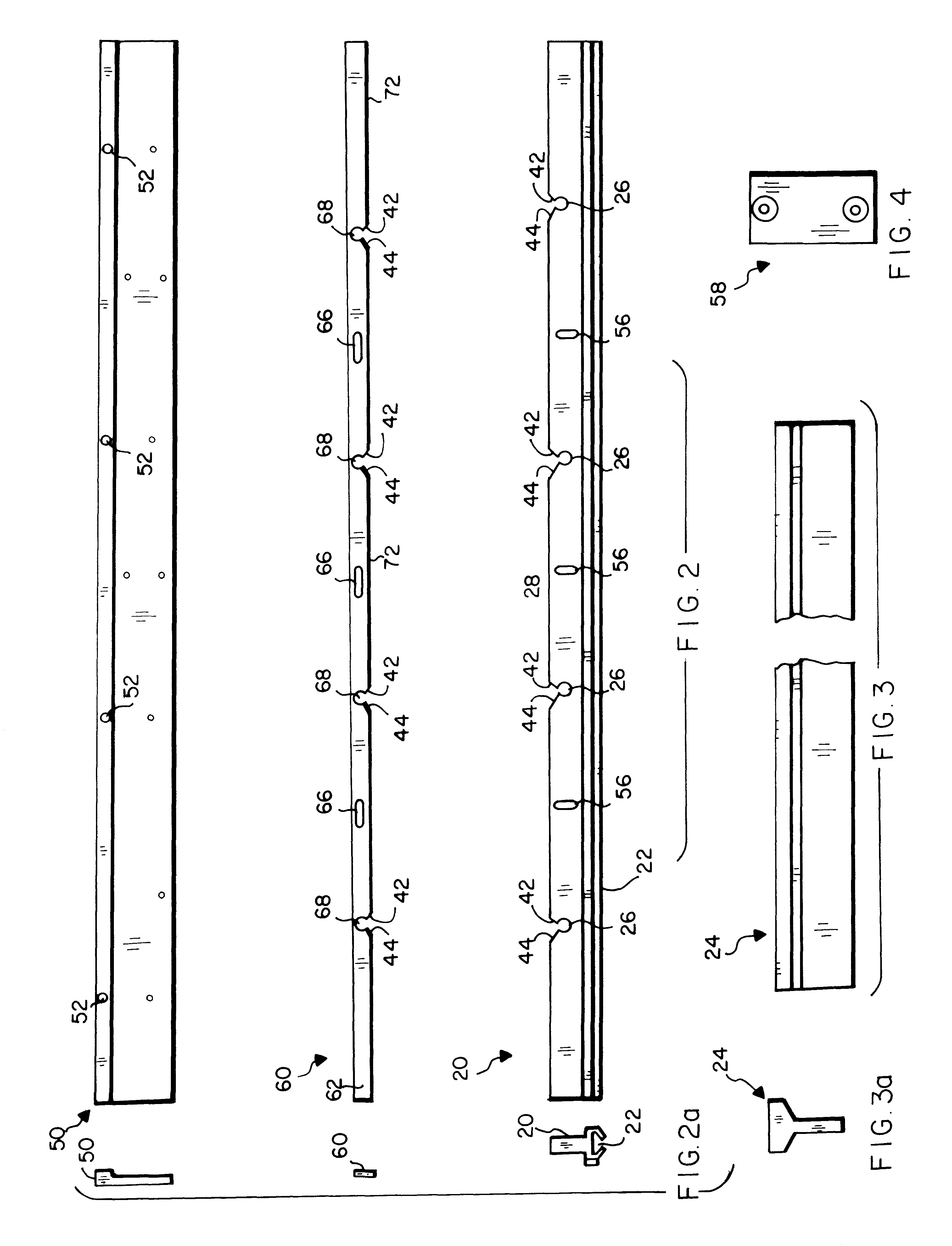
Referring to FIGS. 1-6, an apparatus 10 is disclosed for closing the space between a door 12 lower end 18 and the threshold 14 to obstruct the passage of air through the space. Apparatus 10 includes a gate member 20 which is automatically raised by opening the door 12 to permit the door 12 to swing freely, and which is automatically lowered by closing the door 12, to seal the space between the threshold 14 and the door 12 lower end 18 when the door is closed.

Gate member 20 is preferably an elongate slat having a groove 22 recessed into its lower surface for retaining a resilient sealing strip 24 to sealingly abut the threshold 14. Groove 22 and resilient sealing strip 24 are preferably of T-shaped cross-section to permit sealing strip 24 to slide axially into and out of groove 22 for periodic replacement, and at the same time to prevent sealing strip 24 from sliding downwardly out of groove 22. See FIGS. 3 and 3a.

A slide bar 60 is positioned above and parallel to gate member 20, and...


PUM


Abstract

A sealing apparatus for use with a door which swings over a threshold and has a door lower end, a door face and a door frame, for closing the gap between the door lower end and the threshold, includes a mechanism mounting member; a substantially horizontal gate member for closing the gap; a slide bar positioned above and substantially parallel with the gate member, the slide bar having a protruding end extending laterally from the door toward the door frame to abut the door frame as the door is closed; structure for guiding the slide bar to move laterally relative to the door and to the mounting member; a leaf spring having a leaf spring first end and a leaf spring second end and a leaf spring central segment, the leaf spring first end being engagingly fitted to the slide bar and the leaf spring second end being engagingly fitted to the gate member, where the leaf spring central segment is resiliently pivotable upwardly and laterally to vertically displace the gate member relative to the slide bar; structure for guiding the gate member to move up and down relative to the door; so that closing the door causes the door frame to depress the slide bar protruding end, thereby sliding the slide bar horizontally in one lateral direction and causing the leaf spring to pivot to an increasingly vertical orientation and to thereby lower the attached gate member to make sealing contact with the threshold.

Description

1. Field of the InventionThe present invention relates generally to the field of devices which close the space between the lower end of a closed door and the door threshold to prevent air from passing underneath the door. More specifically the present invention relates to a door lower end sealing apparatus including a gate member which is automatically raised through horizontal movement of a slide bar by opening the door to permit the door to swing freely, and which is automatically lowered by closing the door to seal the space between the threshold and the lower end of the door while the door is closed. A series of leaf springs interconnect the gate member and the slide bar, each leaf spring having a circular loop segment at its upper end and its lower ends. The lower loop segment is snugly fitted into a circular notch in the gate member upper surface and each spring angles upwardly and laterally and is engagingly fitted into a slide bar circular notch in the lower surface of the s...

Claims


Application Information

Patent Timeline
IPC IPC(8): E06B7/18E06B7/21
CPCE06B7/21
Inventor SOWERS, DAVID A.
Owner SOWERS DAVID A
Learn More