Method of controlling a rotary electrical machine, a servo-control system for implementing the method, and a rotary machine fitted with such a system

a technology of servo control system and rotary electrical machine, which is applied in the direction of control system, direct torque control, electrical apparatus, etc., can solve the problems of different output voltage vectors which an inverter can produce, the calculation required for determining the command triplet, and the inability to accurately follow the ideal trajectory in three dimensions. , to achieve the effect of minimizing torque impulses

Inactive Publication Date: 2001-03-06
ALSTOM ENTREPRISE
View PDF7 Cites 13 Cited by
  • Summary
  • Abstract
  • Description
  • Claims
  • Application Information

AI Technical Summary

Benefits of technology

This makes it possible in particular to implement an inverter command strategy in which the distribution of the command vectors makes it possible to make the command orders given to the switches of the inverter symmetrical, thereby leading to a torque harmonic content that leads to minimizing torque impulses on the shaft of the machine.

Problems solved by technology

It is not possible to follow the ideal trajectory in three dimensions accurately insofar as the number of different output voltage vectors which an inverter can produce is limited.
In conventional manner, the calculation required for determining the command triplets, and more particularly the durations during which each command stage should be implemented, are themselves complex and require expensive investment in software and hardware.
Implementing the calculations required to operate a machine controlled by a servo-control system that implements the stages summarized above and for each of the optimized command sequences that are required in succession, implies implementing software and hardware means that, at present, can only be envisaged using machines that are themselves very expensive, such as very high power machines that are unsuitable for controlling more ordinary machines.

Method used


Image

  • Method of controlling a rotary electrical machine, a servo-control system for implementing the method, and a rotary machine fitted with such a system
  • Method of controlling a rotary electrical machine, a servo-control system for implementing the method, and a rotary machine fitted with such a system
  • Method of controlling a rotary electrical machine, a servo-control system for implementing the method, and a rotary machine fitted with such a system

Examples


Embodiment Construction

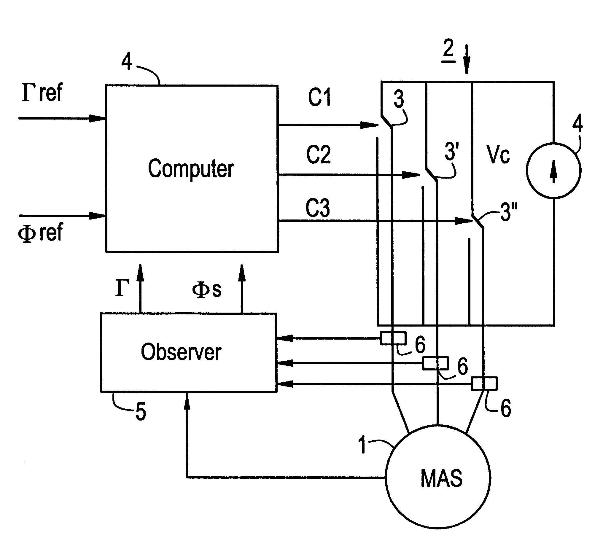
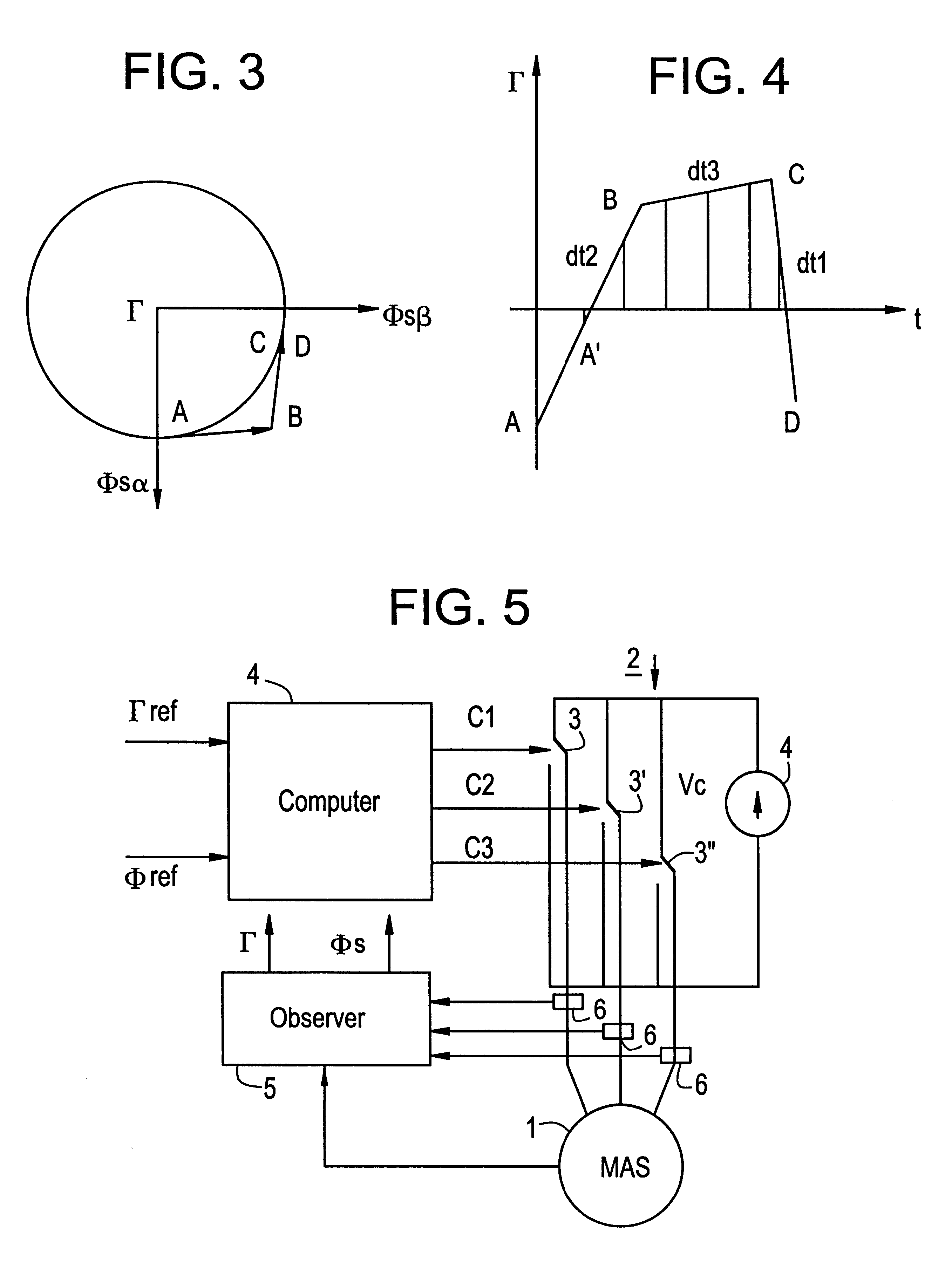
The command method of the invention is designed to be implemented to control the torque of a rotary machine in the context of an assembly of the kind shown diagrammatically in FIG. 5. The assembly comprises a rotary machine 1 having n phases fed with AC by a voltage inverter 2 having n switches of m states each, and thus defining m.sup.n states for the output voltage vector V.sub.S, FIG. 5 showing three switches 3, 3', 3" each having two states.

A servo-control system provides selective and coordinated control of each of the switches by means of signals referenced C1, C2, and C3. These signals are established by means of a computer 4 that is appropriately programmed and which has received indications concerning the reference torque .GAMMA..sub.ref and the reference flux .PHI..sub.ref. The servo-control system also has an observer 5 which deduces the instantaneous values of the electromechanical torque .GAMMA. and of the stator flux .PHI..sub.S from measurements performed by a set of ...


PUM


Abstract

A method of controlling the torque of a rotary machine powered by means of an inverter and servo-controlled by a system having sensors, an observer, and a computer which delivers controls to the switches of the inverter on the basis of values supplied to the observer by the sensors, in the form of sequences of three vectors to bring the torque Γ and the stator flux ΦS of the machine towards reference values for Γref and ΦSref. The measurement sampling period is selected to be equal to the sequence period DTML which corresponds to half the switching period of the inverter. The characteristics of the vectors for each sequence are obtained by solving the following system of equations:in which dΓ / dta and dΓ / dtp are variations over time in torque respectively when an active vector Va or a passive vector Vp is applied, Γn being the present torque, and ta and tp are the respective times during which the vectors are applied.

Description

The invention relates to a method of controlling a rotary machine, to a servo-control system for implementing the method, and to a rotary machine fitted with such a servo-control system.The electrical power supplied by a multiphase AC source to the stator windings of an asynchronous rotary machine serves to magnetize the machine by generating both stator flux .PHI..sub.S and rotor flux .PHI..sub.R therein, and more particularly it serves to create electromagnetic torque .GAMMA. therein.With asynchronous rotary machines it is conventional to make use of stator flux control since that makes it possible in particular to keep a machine in motor operation within the limits within which its electromagnetic state is the best possible, consequently giving rise to the highest efficiency in terms of converting received electrical energy into mechanical energy.Naturally, it is essential to have full control over torque output for a machine that is operating as a motor.In conventional manner, t...

Claims


Application Information

Patent Timeline
Patent Type & Authority Patents(United States)
IPC IPC(8): H02P23/00H02P27/06
CPCH02P21/005H02P23/004Y10S388/909H02P21/30H02P23/30
Inventor THOMAS, JEAN-LUCDIONNET, VINCENTPOULLAIN, SERGE
Owner ALSTOM ENTREPRISE
Why Eureka
Try Eureka