Vehicle guidance assembly and method

a technology of vehicle guidance and assembly, which is applied in the direction of transportation and packaging, television systems, instruments, etc., can solve the problems of inability to maintain the vehicle, and one small error in the judgement of the driver, and achieve the effect of saving lives

Inactive Publication Date: 2001-03-06
WHITE II LOCKE
View PDF12 Cites 51 Cited by
  • Summary
  • Abstract
  • Description
  • Claims
  • Application Information

AI Technical Summary

Benefits of technology

to provide a vehicle guidance assembly which utilizes an image projecting device, such as a laser module or other high-intensity light source, to project a visual image downwardly from the vehicle and outwardly onto the road surface for being readily viewed by the driver.

Problems solved by technology

One common problem recognized by drivers of trucks and other large vehicles is the ability to maintain the vehicle in the center of the lane, particularly at night and after several hours of constant driving.
Many "long haul" truck drivers suffer mental fatigue and stress, and often drive tired putting their own safety and the safety of others on the road at risk.
One small error in judgement by the driver can cost lives.

Method used


Image

  • Vehicle guidance assembly and method
  • Vehicle guidance assembly and method
  • Vehicle guidance assembly and method

Examples


second embodiment

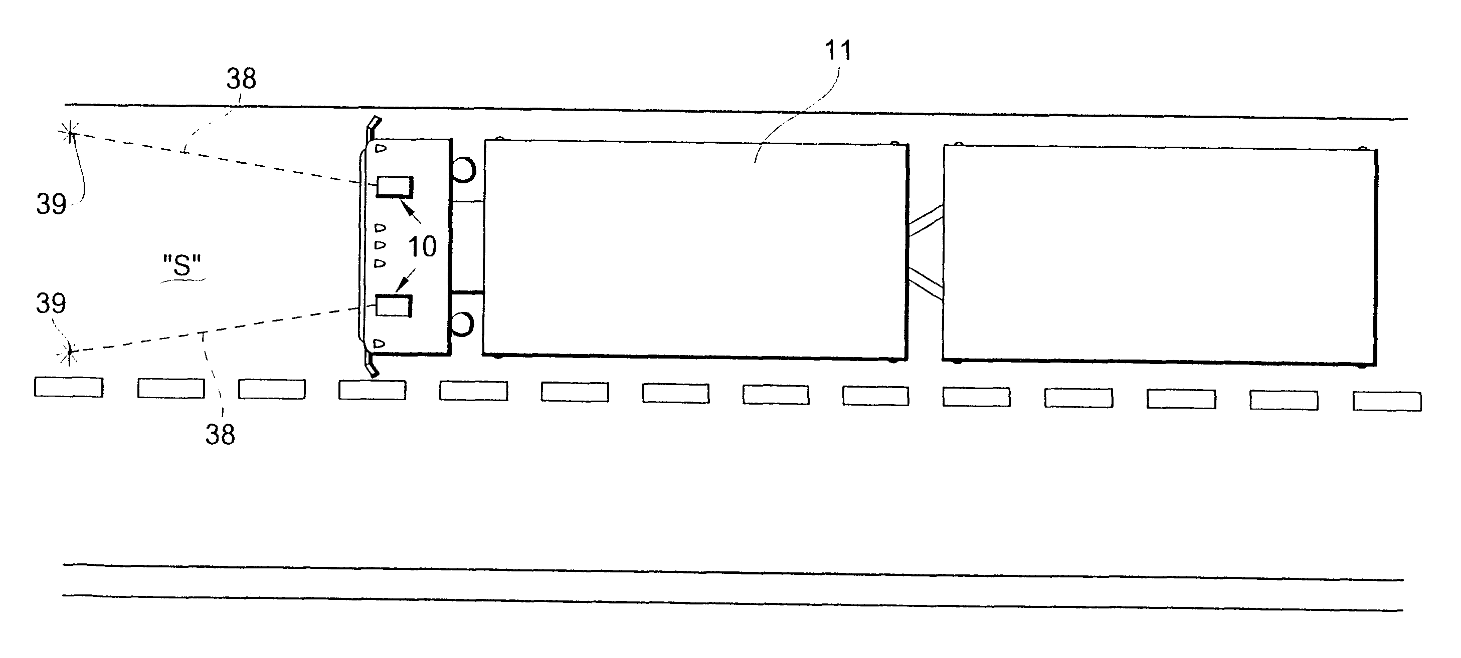
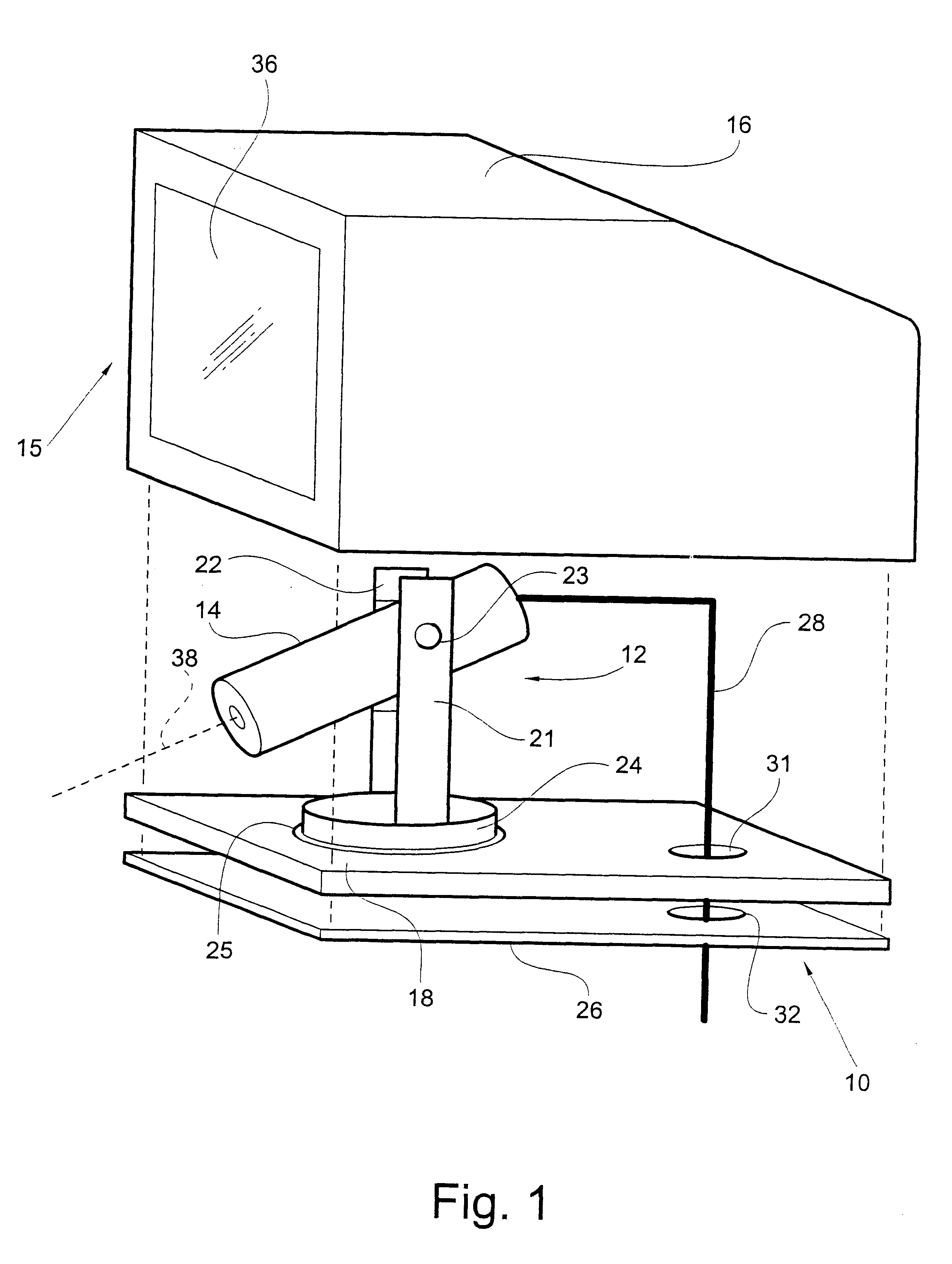
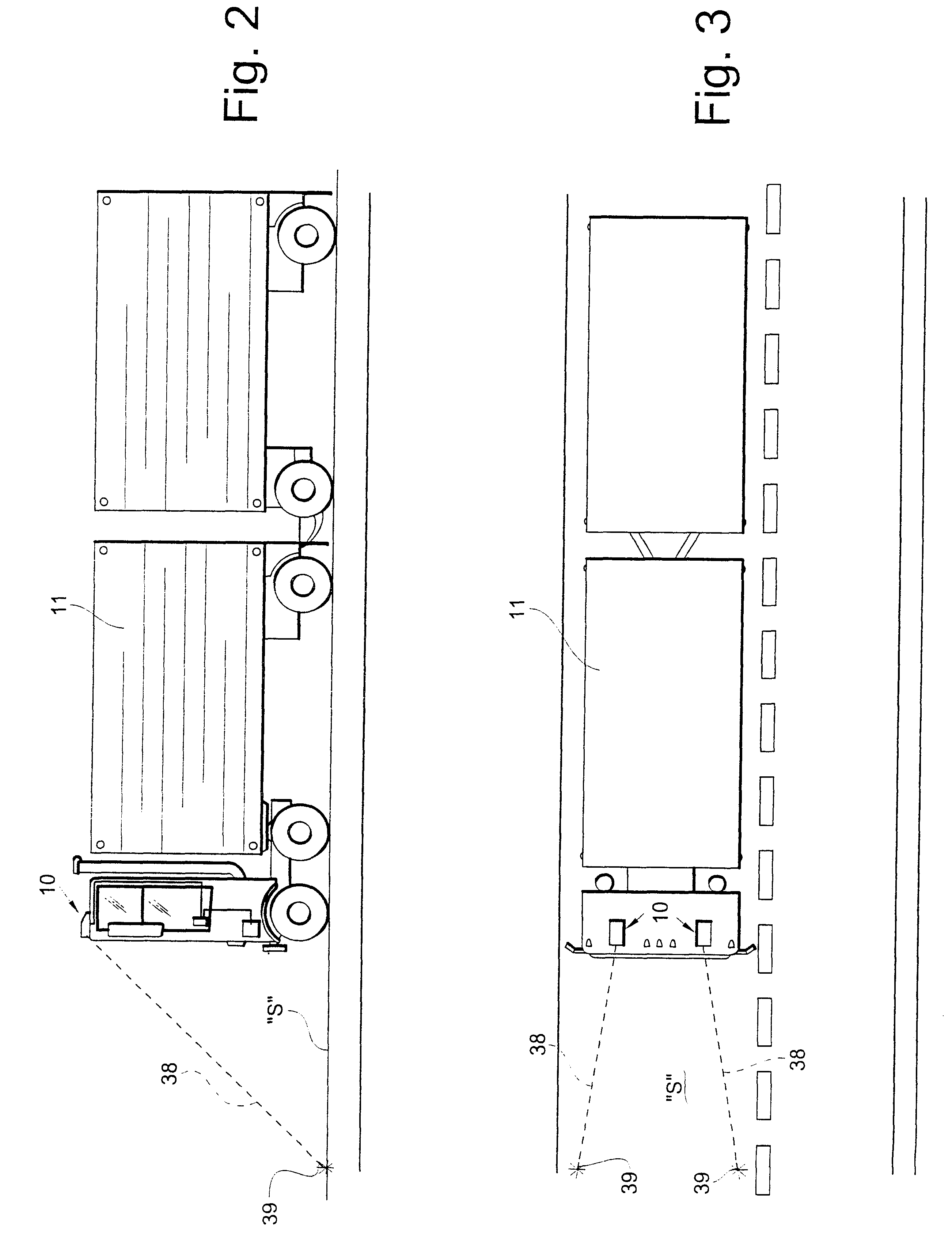
the guidance assembly 40 is shown in FIGS. 4 and 5. As previously described, the guidance assembly 40 includes an upstanding adjustable holder 42, a laser module 44 carried by the holder 42, and a protective housing 45 with a removable cover 46 and mounting plate 48. The holder 42 includes spaced vertical supports 51 and 52, a locking pivot pin 53, and an annular swivel base 54. The swivel base 54 is closely received within a complementary-shaped opening 55 formed in the mounting plate 48 of the housing 45. A rubber gasket 56 is positioned between the mounting plate 48 and vehicle 11 to create a seal preventing water from entering the housing 45 and damaging the laser module 44 during operation of the vehicle 11. The cover 46 has a window 57 for allowing passage of the laser beam 58 from the laser module 44 through the housing 45 and downwardly onto the road surface "S".

The electrical power cable 61 is connected to the laser module 44 and a ground-fault interrupter 62, and extends t...

third embodiment

the guidance assembly 80 is shown in FIG. 6. The guidance assembly includes an upstanding adjustable holder 82, a laser module 84 carried by the holder 82, and a protective housing 85 with a removable cover 86 and mounting plate 88. The holder 82 includes spaced vertical supports 91 and 92, a locking pivot pin 93, and an annular swivel base 94. The swivel base 94 is closely received within a complementary-shaped opening 95 formed in the mounting plate 88 of the housing 85. A rubber gasket 96 is positioned between the mounting plate 88 and vehicle to create a seal preventing water from entering the housing 85 and damaging the laser module 84 during operation of the vehicle. The cover 86 has a window 97 which allows passage of the laser beam 98 from the laser module 84 outwardly through the housing 85 and downwardly onto the road surface.

The power cable 101 is electrically connected to the laser module 84 and a mercury switch 102, and extends through aligned openings 104 and 105 in th...

fourth embodiment

the guidance assembly 110 is shown in FIGS. 7 and 8. The guidance assembly 110 includes an upstanding adjustable holder 112, a laser module 114 carried by the holder 112, and a protective housing 115 with a removable cover 116 and mounting plate 118. The holder 112 includes spaced vertical supports 121 and 122, a locking pivot pin 123, and an annular swivel base 124. The swivel base 124 is closely received within a complementary-shaped opening 125 formed in the mounting plate 118 of the housing 115. A rubber gasket 126 is positioned between the mounting plate 118 and vehicle 11 to create a seal preventing water from entering the housing 115 and damaging the laser module 114 during operation of the vehicle 11. The cover 116 has a window 127 for allowing passage of the laser beam 128 from the laser module 114 outwardly through the housing 115 and downwardly onto the road surface "S".

The power cable 131 is electrically connected the laser module 114 and an electrical interrupter 132, a...


PUM


Abstract

A vehicle guidance assembly visually indicates the anticipated path of a moving vehicle to a driver of the vehicle. The assembly includes an image projection device for projecting a visual image outwardly from the vehicle and downwardly onto a surface to be travelled by the vehicle. The image defines a reference mark on the surface for being readily viewed by the driver. A mounting member mounts the image projection device on a surface of the vehicle.

Description

TECHNICAL FIELD AND BACKGROUND OF THE INVENTIONThis invention relates to a vehicle guidance assembly and method. The invention is especially applicable for use on large vehicles, such as tractor-trailers, buses, vans, RVs, and the like, to enhance the ability of the driver to maintain the vehicle on its proper course over a roadway. The invention creates visible reference marks on the road surface which clearly and distinctly define, for example, the outermost side edges of the vehicle.One common problem recognized by drivers of trucks and other large vehicles is the ability to maintain the vehicle in the center of the lane, particularly at night and after several hours of constant driving. Many "long haul" truck drivers suffer mental fatigue and stress, and often drive tired putting their own safety and the safety of others on the road at risk. These drivers must constantly make split-second decisions concerning the actual and anticipated path of their vehicle. Driving a truck invo...

Claims


Application Information

Patent Timeline
Patent Type & Authority Patents(United States)
IPC IPC(8): B60R1/00H04N7/18
CPCB60R1/00H04N7/181
Inventor WHITE, II, LOCKE
Owner WHITE II LOCKE
Why Eureka
Try Eureka