Pipe structure and method of manufacture

a technology of pipe structure and pipe section, applied in the direction of pipes, mechanical equipment, other domestic objects, etc., can solve the problems of inability to use the pipe section, inefficient labor cost and time, and soften the pipe portion, so as to achieve effective strengthening of the structure, resist deformation, and increase the effect of strength

Inactive Publication Date: 2001-03-13
HANCOR
View PDF51 Cites 72 Cited by
  • Summary
  • Abstract
  • Description
  • Claims
  • Application Information

AI Technical Summary

Benefits of technology

It is therefore an object of the invention to provide a pipe section having a female end with a strengthened periphery.
It is still another object of the invention to provide a pipe assembly which is efficiently and cost-effectively fabricated in the field and is reliably sealed against leakage.
In another aspect, the invention is a pipe assembly for accommodating fluid flow therethrough, which includes a first pipe section comprising a segment of polymeric material configured as a conduit and having a male end and a female end, said first pipe section's female end being flared and being strengthened by a reinforcing structure formed integrally of said material around the periphery of said female end, and a second pipe section comprising a segment of polymeric material configured as a conduit and having a male end and a female end, said male end of said second pipe section being in the female end of the first pipe section such that fluid may flow from one of said sections into the other.
Substantial benefits are conferred by practice of the invention. The provision of a reinforcing structure integral with the subject pipe section, proximate the periphery of the female end, effectively strengthens the structure so that it maintains its desired shape, resists deformation during storage before use, and can withstand rough handling during connection of other piping to it. The pipe assembly incorporating such pipe section is cost effectively fabricated in the field and has increased strength at the point of interface during the connection operation, with the result that such operation is made easier and more efficient. And, the method and apparatus for making the pipe section, as well as the method for making the aforementioned pipe assembly, of the invention are correspondingly convenient and cost effective.

Problems solved by technology

One problem presented in such pipes derives from the fact that, during fabrication, the material from which the pipe is made is heated, and then cooled.
If the pipe is then exposed to heat, even such as that of strong sunlight, it may cause enough warming to soften portions of the pipe.
This flowered structure presents problems when the pipe sections are to be assembled, since the puckering of this shape may make the female end of the pipe too small to easily accommodate the male end of the next pipe section.
This is inefficient in terms of labor costs and time.
Moreover, the flowering can render the pipe section completely unusable.

Method used


Image

  • Pipe structure and method of manufacture
  • Pipe structure and method of manufacture
  • Pipe structure and method of manufacture

Examples


Embodiment Construction

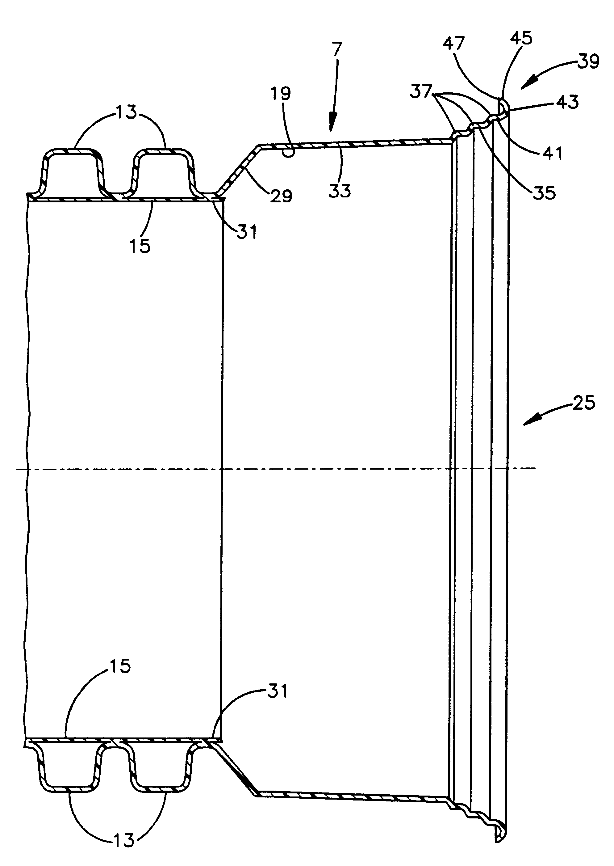
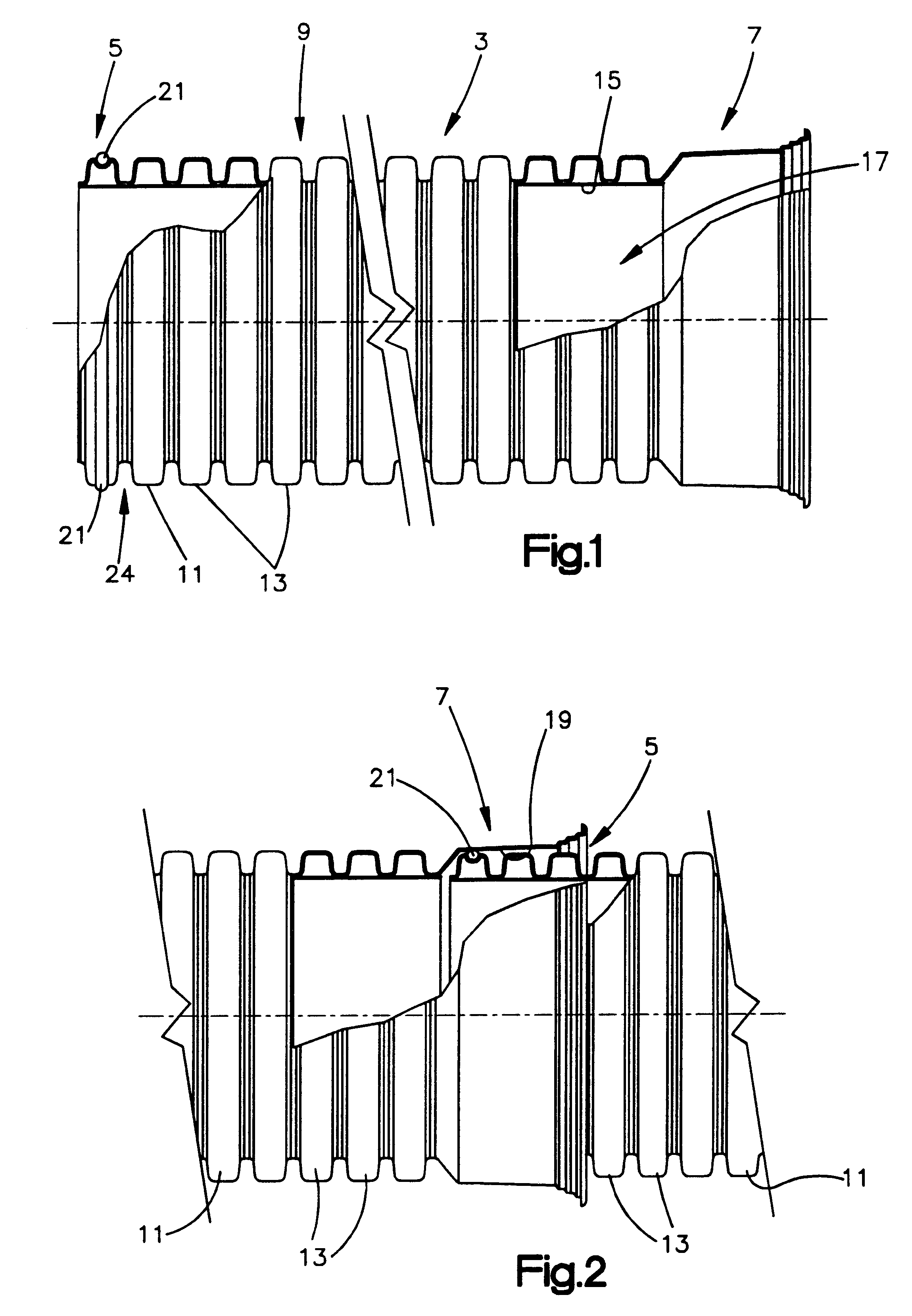
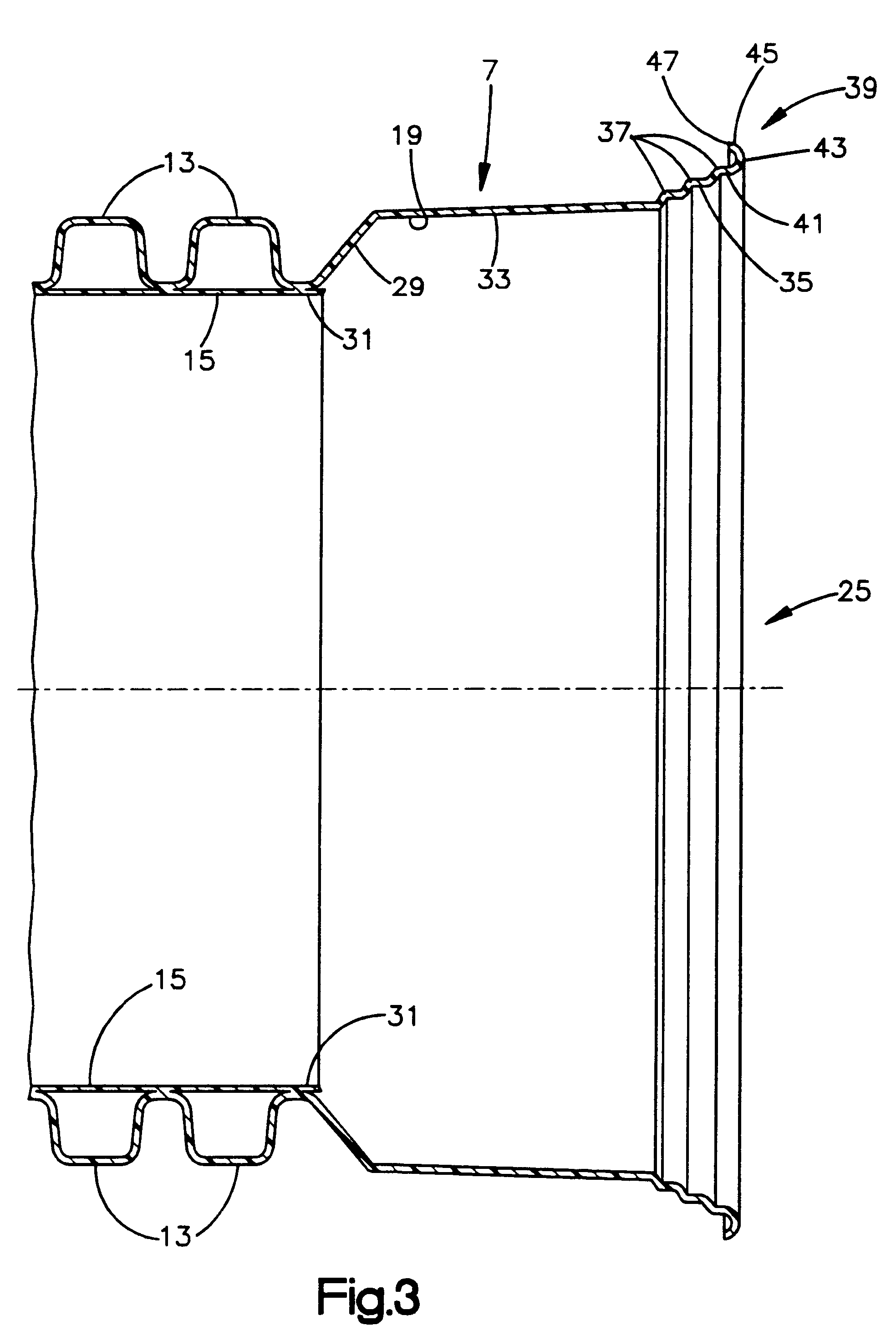
A central feature of our invention is formation of the integral reinforcing member on the female end of a subject pipe section. This member reinforces the female end's peripheral edge so that it can withstand rough contact, jostling and the like when a male end of another pipe section is inserted and moved around to secure alignment pursuant to connection of the pipe sections. Typically, practice of the present invention results in attainment of a hoop strength at the reinforced female end of at least 10, and preferably at least 15, pounds (e.g. for 4-inch diameter conduit) and in some cases 50, and preferably at least 80, pounds (e.g., for 12-inch diameter conduit), hoop strength being defined as the amount of force needed to laterally compress a pipe by 5% of its diameter. Moreover, the reinforcing member strengthens the female end of a subject pipe section, especially when flared, against deformation resulting from flowering by providing a skeletal frame which holds the end in it...


PUM

PropertyMeasurementUnit
angleaaaaaaaaaa
angleaaaaaaaaaa
angleaaaaaaaaaa

Abstract

A pipe section formed of a polymeric material which has a substantially constant thickness throughout, the terminal edge of the female connection having a reinforcement structure which rigidifies the end of the female connection and prevents deformation, the pipe section preferably having a flared end, and the reinforcement structure preferably being a semicircular channel formed at the end of the pipe section by a mandrel after initial extrusion of the pipe section; along with a method and apparatus for forming the pipe section, a pipe assembly including such pipe section, and a method of forming the pipe assembly.

Description

This invention relates to pipes made from polymeric material, and more particularly to pipes made as segments which are assembled into larger pipe systems during installation.During recent years, it has become more and more common for pipes for the transmission of fluids to be made from plastic materials.Non-metal materials are made into various types of pipes by several methods. For instance, it is known to extrude PVC into various shaped pipes. Another more economical method is the corrugated pipe technique, which uses blow mold and vacuum mold techniques to produce a pipe which is formed as extruded tubes of a polymer such as HDPE (high density polyethylene). Systems for fabricating such corrugated pipes are sold by Corma, Inc. of Concord, Ontario. A system of this type is also described in U.S. Pat. No. 5,296,188, which is herein incorporated by reference.Polymer material pipes are generally manufactured as continuous extrusions which are then cut into sections. Frequently, each...

Claims


Application Information

Patent Timeline
Patent Type & Authority Patents(United States)
IPC IPC(8): B29C47/06B29C57/00F16L11/00F16L11/15B29C57/12B29C48/09B29C48/13B29C48/15B29C48/18
CPCB29C47/0023B29C47/0033B29C47/06B29C57/00F16L11/15B29C47/02B29C57/12Y10T29/49879B29L2023/18Y10S285/903Y10S425/218Y10T29/49872B29K2023/06B29C48/15B29C48/09B29C48/13B29C48/18
Inventor SIFERD, ROGER LEEANKROM, MATTHEW C.PORTER, LARRY E.
Owner HANCOR
Why Eureka
Try Eureka