Hot tap fluid blaster apparatus and method of using same

a technology of hot tapping and fluid blaster, which is applied in the direction of branching pipes, cleaning using liquids, transportation and packaging, etc., can solve the problems of clogging or plugging the pipeline, paraffin blockage, and waxy paraffin

Inactive Publication Date: 2001-03-13
SAIPEM AMERICA
View PDF13 Cites 84 Cited by
  • Summary
  • Abstract
  • Description
  • Claims
  • Application Information

AI Technical Summary

Problems solved by technology

A paraffin blockage is caused by the paraffin precipitating out of the crude oil and packing in the pipe.
The paraffin is very waxy and can clog or plug the pipeline.
Plugging of pipelines is a well known problem.
Nonetheless, plugging of pipelines does occur.

Method used


Image

  • Hot tap fluid blaster apparatus and method of using same
  • Hot tap fluid blaster apparatus and method of using same
  • Hot tap fluid blaster apparatus and method of using same

Examples


Embodiment Construction

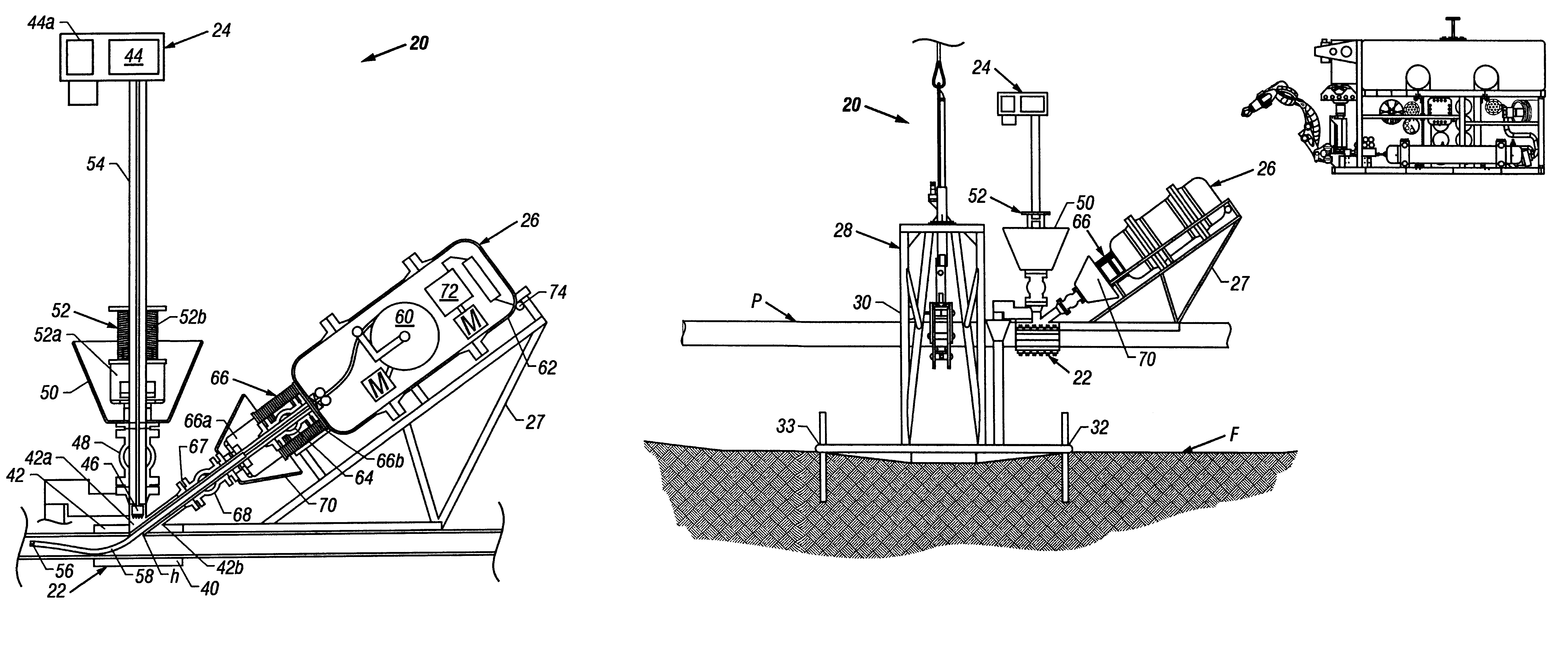
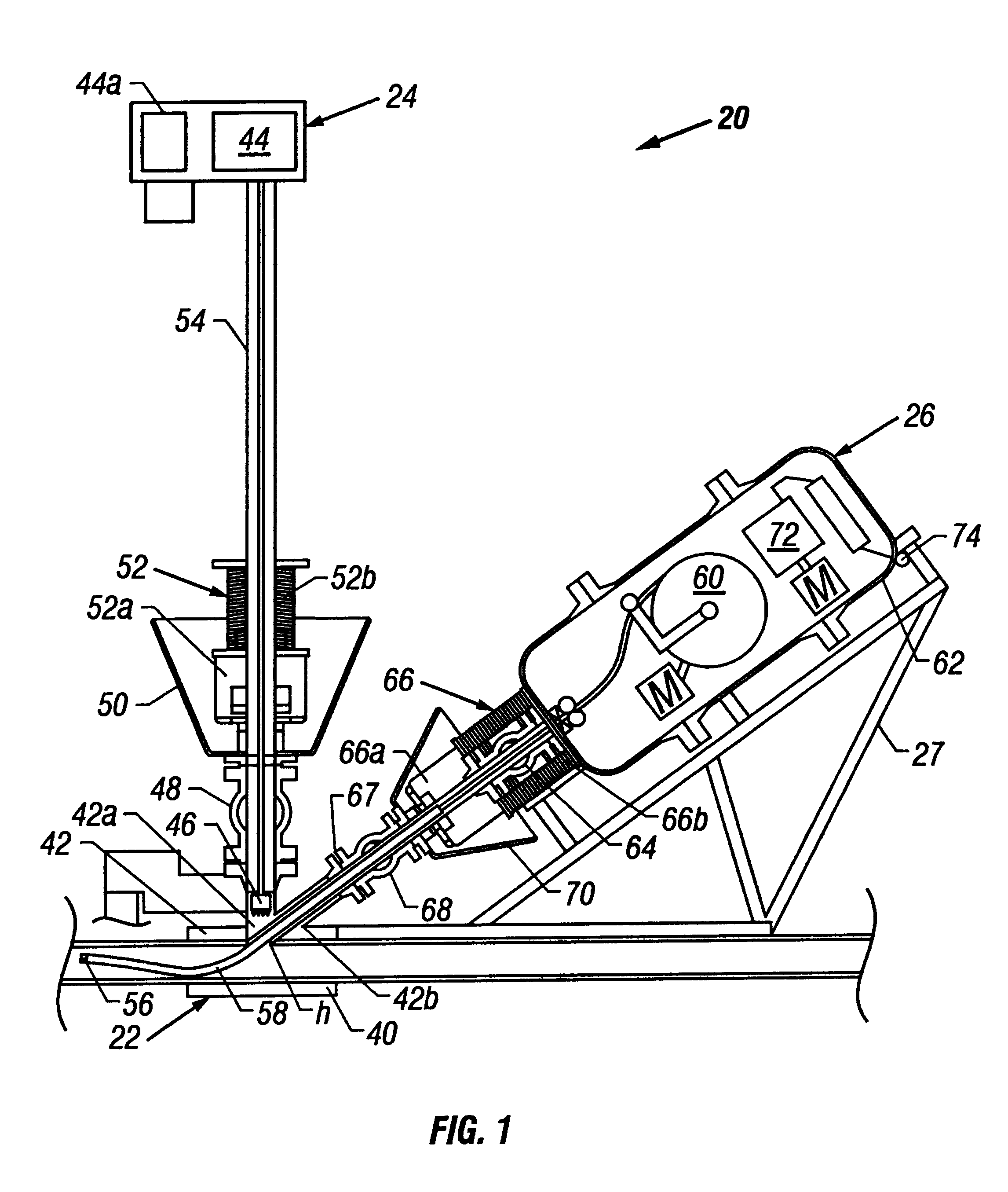
The hot tap fluid blaster apparatus, generally designated as reference 20, will now be described with specific reference to the drawings. Referring to FIGS. 1 and 8, the hot tap fluid blaster apparatus 20 comprises a hot tap saddle or tee 22, a drill assembly 24, a fluid blaster assembly 26, and a support frame assembly 28 (FIG. 8).

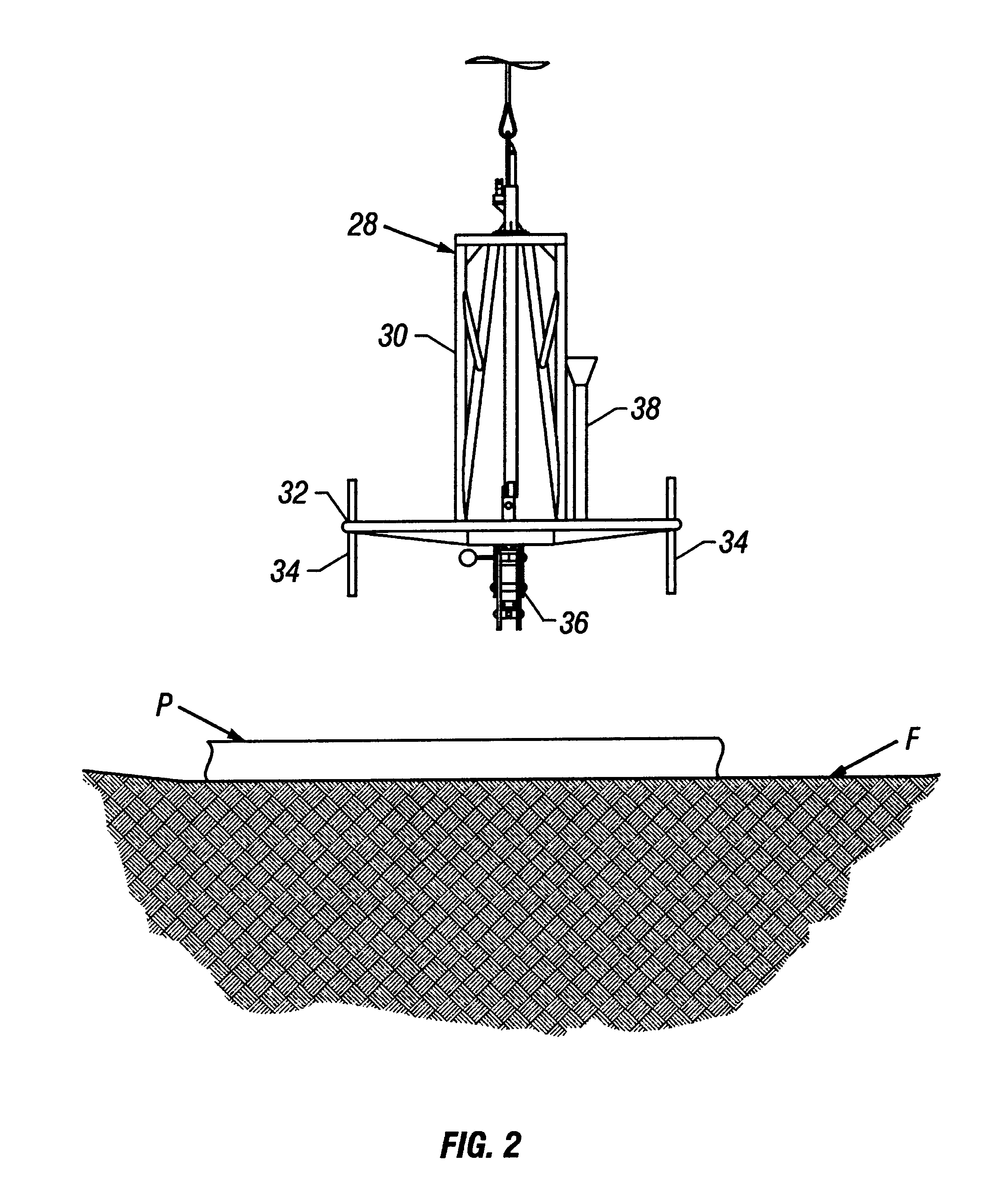
Referring to FIGS. 2 and 8, the support frame assembly 28 includes an upright framework 30 attached to a base 32 adapted to vertically support the upright framework 30 on the sea floor F. As shown in FIG. 2, the support frame assembly 28 may include a plurality of vertical legs 34 attached to the base 32 to provide support to the support frame assembly 28. The support frame assembly 28 includes a lower pipe gripper 36 for gripping onto the pipeline P. The pipe gripper 36 is preferably hydraulically controlled. The support frame assembly 28 also includes a vertical guide member 38 for reasons which will be explained below. It is to be understood that the s...


PUM


Abstract

A apparatus and method of using the apparatus for removing a blockage in a subsea pipeline without retrieval of the pipeline to the surface. The apparatus components include a hot tap saddle, a drill assembly, a fluid blaster assembly and a support frame. The hot tap saddle component has a first portion and a second portion, with the first and second portions being configured to clampingly engage in a sealing relationship to the subsea pipeline. The first portion of the saddle includes a first and second opening with the first opening extending generally upwardly and configured for connecting to a drill assembly and the second opening being positioned generally at an angle to the first opening and configured for connecting to a fluid blaster assembly. The fluid blaster assembly including a nozzle, a hose and a high pressure pump with the fluid blaster assembly being contained within a pressure vessel. The fluid blaster assembly is configured for mounting to the second opening of the hot tap saddle component. The support frame assembly is configured for gripping and supporting the subsea pipeline on the sea floor while the fluid blaster assembly operates to remove a blockage in the subsea pipeline with the pipeline being under pressure and without severing the pipeline.

Description

1. Field of the InventionThe present invention relates generally to subsea pipeline hot tapping operations, and more particularly relates to subsea pipeline fluid blasting operations conducted through a pipeline hot tap.2. Description of the Related ArtSubsea crude oil pipelines are often plugged by localized accumulations of paraffin, hydrate and other deposits. A paraffin blockage is caused by the paraffin precipitating out of the crude oil and packing in the pipe. The paraffin is very waxy and can clog or plug the pipeline. Plugging of pipelines is a well known problem. Pipeline operators attempt to prevent this problem by requiring regular pigging of the pipeline or through the injection of solvents or chemicals in the pipeline to prevent paraffin build-up.Nonetheless, plugging of pipelines does occur. Typically, the paraffin blockage is removed from a subsea pipeline by raising the pipeline to the surface and severing the pipeline. The pipeline can then be mechanically cleaned ...

Claims


Application Information

Patent Timeline
Patent Type & Authority Patents(United States)
IPC IPC(8): F16L1/26
CPCF16L1/26F16L41/06Y10T137/612Y10T137/0435Y10T137/0424
Inventor BATH, WILLIAM R.HETTINGER, FREDRIC L.CLARK, TIMOTHYNOCE, ROBERTO
Owner SAIPEM AMERICA
Why Eureka
Try Eureka