Surface preparation device

a surface preparation and surface technology, applied in the direction of grinding drive, grinding machine components, manufacturing tools, etc., can solve the problems of unsightly cross-grain scratch patterns on the surface of workpieces, time-consuming and expensive, and laborious process,

Inactive Publication Date: 2001-03-13
DREES EDWARD
View PDF17 Cites 24 Cited by
  • Summary
  • Abstract
  • Description
  • Claims
  • Application Information

AI Technical Summary

Problems solved by technology

The major drawback of many of these machines is that they often leave unsightly cross-grain scratch patterns in the surface of the workpiece.
However, this process is very labor intensive, time consuming and expensive.
Further, hand sanding generally fails to produce a uniform surface particularly on relatively large surfaces, such as cabinet doors.
However, as the speeds of rotation increase bearing wear, including wear on bearings attached to the platen, can become excessive resulting in frequent bearing failure to mitigate against excessive platen bearing wear, the platen size of the sander must, of necessity, be kept small thereby limiting the effectiveness of the machine for use in high volume production processes.

Method used


Image

  • Surface preparation device
  • Surface preparation device
  • Surface preparation device

Examples


Embodiment Construction

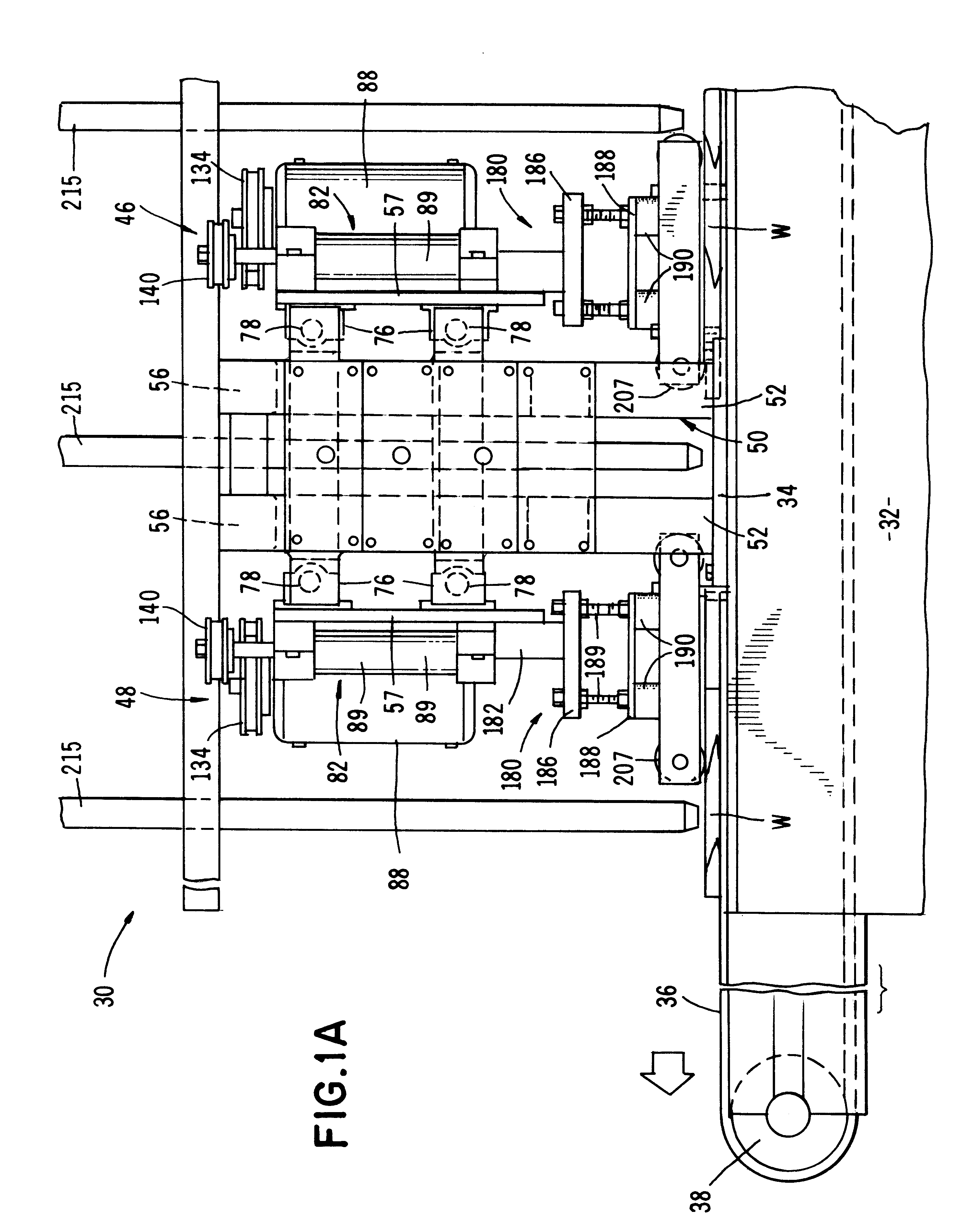
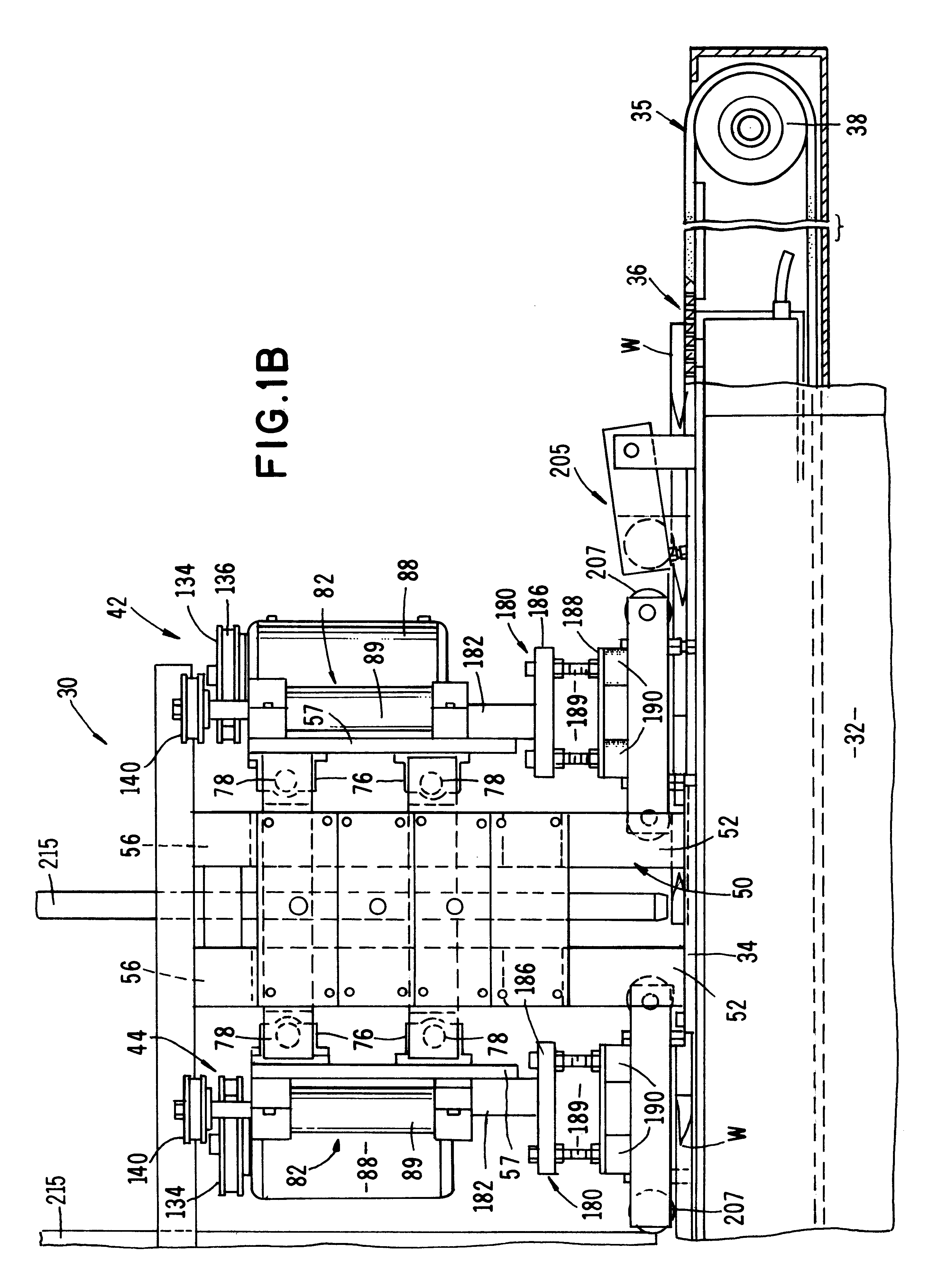
Referring to the drawings and particularly to FIGS. 1A, 1B, 2A and 2B, the apparatus of one form of the surface preparing apparatus of the invention is there shown and generally designated by the numeral 30. The apparatus here comprises a stationary main frame 32 having transversely spaced-apart, generally horizontally extending mounting surfaces 34 (FIG. 2A). Connected to main frame 32 is a vacuum type conveyer subsystem 35 which includes a perforated endless conveyer belt 36. Belt 36 travels around rollers 38 provided at either end of the mainframe which rollers are driven in a conventional manner by an electric motor or other suitable drive means. 1n a manner presently to be described, belt 36 functions to transport the workpieces "W" (FIGS. 1A, 1B and 2) through the machine at a uniform rate. The vacuum type conveyor subsystem is of standard design and of a character well known to those skilled in the art.

The surface preparing apparatus itself includes four longitudinally spaced...


PUM


Abstract

A production type surface finishing apparatus for finishing the surfaces of work-pieces such as cabinet doors and the like which include a plurality of relatively large, very lightweight finishing platens that are simultaneously movable in both a reciprocal and an orbital-like motion. The platen is moved in a reciprocal motion by a first motion-imparting mechanism and is simultaneously moved in a high-frequency, orbit-like motion by a second motion-imparting mechanism that includes shafts which are rotated at relatively high rates of speed. The shafts, and the motors which drive them, are mounted on platforms which are reciprocally movable relative to the main frame of the device. Connected to the rotating shafts by specially designed elastomeric sleeve-like members are specially configured, ring-like member which are provided with a plurality of circumferentially spaced apertures along one edge of the ring. The rings are, in turn, connected to the platen assemblies by novel shaft and bearing assemblies. The platens are also connected to the reciprocating platforms of the apparatus by novel isolated sleeves.

Description

1. Field of the InventionThe present invention relates generally to surface preparation. More particularly, the invention concerns an improved surface preparation apparatus for forming a very fine surface on wooden workpieces such as cabinet doors and the like.2. Discussion of the Prior ArtA number of different kinds of handheld as well as volume production type machines for preparing surfaces of various types of workpieces have been suggested in the past. These machines typically use a sanding belt entrained around a sanding platen. The major drawback of many of these machines is that they often leave unsightly cross-grain scratch patterns in the surface of the workpiece. Frequently hand sanders such as those disclosed in U.S. Pat. No. 4,487,010 issued to Dicke are used to remove the unacceptable cross-scratches. However, this process is very labor intensive, time consuming and expensive. Further, hand sanding generally fails to produce a uniform surface particularly on relatively ...

Claims


Application Information

Patent Timeline
Patent Type & Authority Patents(United States)
IPC IPC(8): B24B47/00B24B47/12B24B7/20B24B7/28
CPCB24B7/28B24B47/12
Inventor DREES, EDWARD
Owner DREES EDWARD
Why Eureka
Try Eureka