Method of making a glass fiber preform with adjusting a spacing while increasing acceleration of a starting glass powder

a technology of glass fiber and preform, which is applied in the field of making a glass fiber preform, can solve the problems of limited quantity of glass powder inserted into the plasma and deposited on the primary preform

Inactive Publication Date: 2001-03-20
ALCATEL LUCENT SAS
View PDF11 Cites 81 Cited by
  • Summary
  • Abstract
  • Description
  • Claims
  • Application Information

AI Technical Summary

Benefits of technology

According to the invention, the drawback due to the limitation of powder penetration depth into the plasma flame is eliminated or at least greatly reduced by making available a method and apparatus in which the rate at which glass preforms are manufactured in a system us

Problems solved by technology

In such a method, the quantity of glass powder inserted into the plasma and deposited on the

Method used


Image

  • Method of making a glass fiber preform with adjusting a spacing while increasing acceleration of a starting glass powder
  • Method of making a glass fiber preform with adjusting a spacing while increasing acceleration of a starting glass powder

Examples


Embodiment Construction

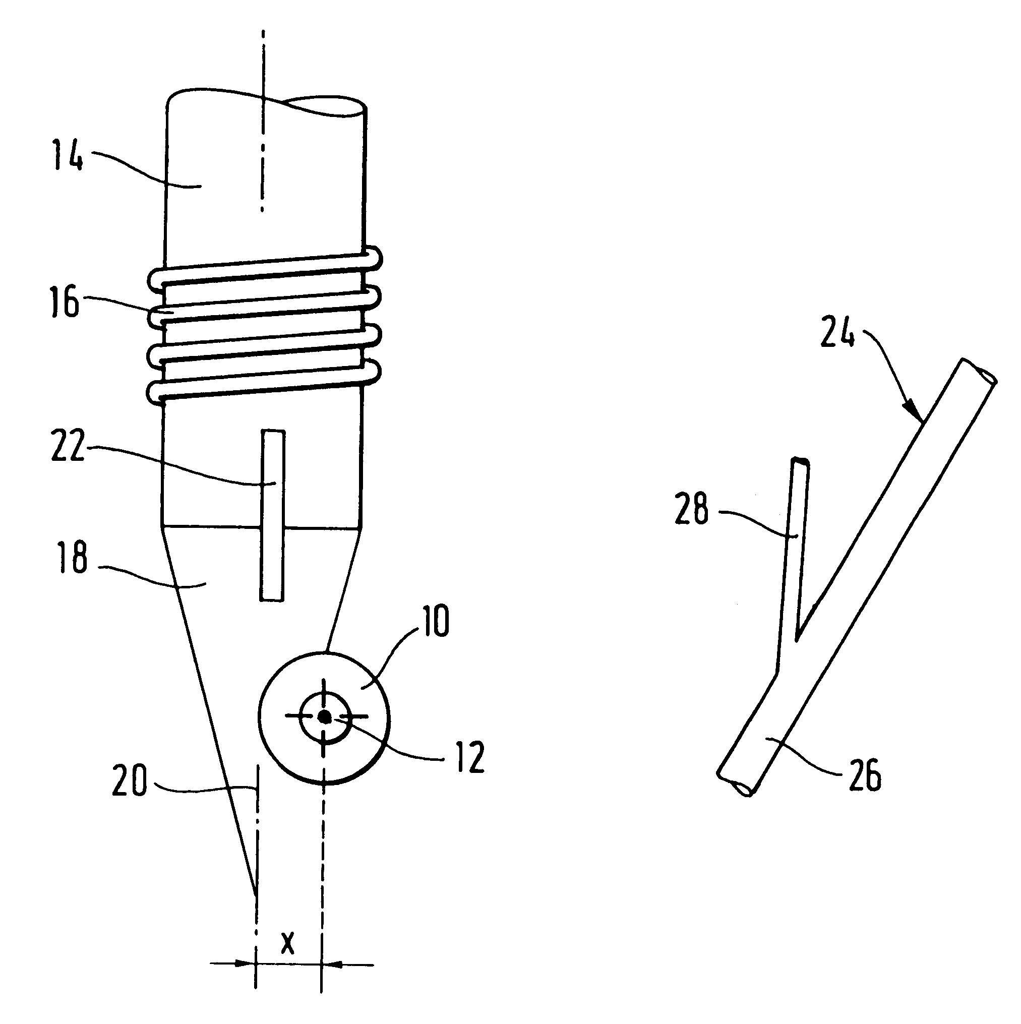
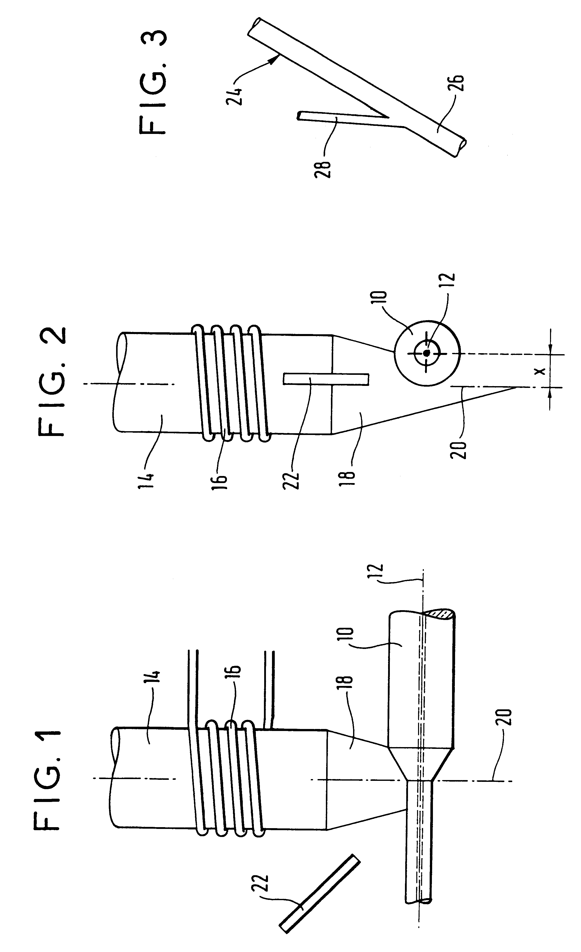
FIGS. 1 and 2 show an apparatus for manufacturing glass fiber preforms which can be used in a method of manufacturing preforms of the plasma torch type having gravity feed. More precisely, the glass fiber preform 10 is made on a primary preform of cylindrical shape and circular section which rotates about its own axis 12 and which moves parallel to its axis, from left to right in FIG. 1. From a plasma torch 14 which includes a tube surrounded by an induction heater winding 16, a flame 18 of plasma is projected towards the preform 10. The plasma flame has an axis 20.

Glass powder of particle size lying in the range 0.1 mm to 0.2 mm, for example, is inserted under gravity via a tube 22 from outside the plasma flame 18, above the preform 10. The powder grains which penetrate into the flame are melted and are applied to the preform whose diameter increases.

It will be observed in FIG. 2 that the axis 20 of the flame is offset from the axis 12 of the preform, these two axes being separated...


PUM

PropertyMeasurementUnit
Flow rateaaaaaaaaaa
Mass flow rateaaaaaaaaaa
Flow rateaaaaaaaaaa

Abstract

The invention relates to manufacturing glass fiber preforms. It relates to a method comprising rotating preform about its own axis, and displacing a plasma torch in translation relative to the preform in a direction parallel to the axis of the preform, the axes of the flame and of the preform and being offset by a certain distance, and then inserting glass powder into the plasma flame under gravity. According to the invention, the glass powder is accelerated before penetrating into the plasma flame by means of an accelerator gas, and the offset distance between the axes is reduced with increasing acceleration of the powder. The invention is applicable to manufacturing glass fibers, and in particular optical fibers.

Description

The invention relates to manufacturing glass fiber preforms, and in particular optical fiber preforms, and it relates in particular to a method and apparatus making it possible specifically to increase the rate at which such preforms are manufactured.Document FR-A-2 253 723 describes a method of preparing a preform for an optical waveguide in which a plasma torch projects glass powder which is injected into the base of the flame by a carrier gas. A flow of carrier gas is created so as to move the glass powder along a substantially horizontal elongate path. More precisely, in the absence of carrier gas, the glass powder does not advance towards the plasma torch so the plasma flame does not contain glass powder. That constitutes a method of pneumatically injecting glass powder.Also known, from document GB-A-2 134 696 is a method of manufacturing a preform which is similar to the method of the first-mentioned document. A mechanically measured quantity of silica glass powder is inserted...

Claims


Application Information

Patent Timeline
IPC IPC(8): C03B37/012G02B6/00C03B37/018
CPCC03B37/01291
Inventor DROUART, ALAINGOUEZ, BENOITRIPOCHE, PIERRE
Owner ALCATEL LUCENT SAS
Why Eureka
Try Eureka