Instant-on vented tank valve with manual override and method of operation thereof

a vented tank valve and manual override technology, which is applied in the direction of machine/engine, container discharging method, pressure relieving device on sealing face, etc., can solve the problems of venting the tank, motor vehicle cannot be operated, and extreme difficulty in repairs

Inactive Publication Date: 2001-03-20
WESTPORT POWER
View PDF32 Cites 51 Cited by
  • Summary
  • Abstract
  • Description
  • Claims
  • Application Information

AI Technical Summary

Problems solved by technology

Some previous valves are mounted internally and, when the valve malfunctions, it is extremely difficult to make repairs, to vent the tank or to remove the gas pressure from the valve by shutting off the flow of gas from the tank to the valve.
Further, if the valve fails, with some previous designs, the motor vehicle cannot be operated.
Still further, with previous valves, there is a relatively large time lapse from the turning of the key until the starting of the engine as it can take the valve eighteen seconds or longer to fully open.

Method used


Image

  • Instant-on vented tank valve with manual override and method of operation thereof
  • Instant-on vented tank valve with manual override and method of operation thereof
  • Instant-on vented tank valve with manual override and method of operation thereof

Examples


Embodiment Construction

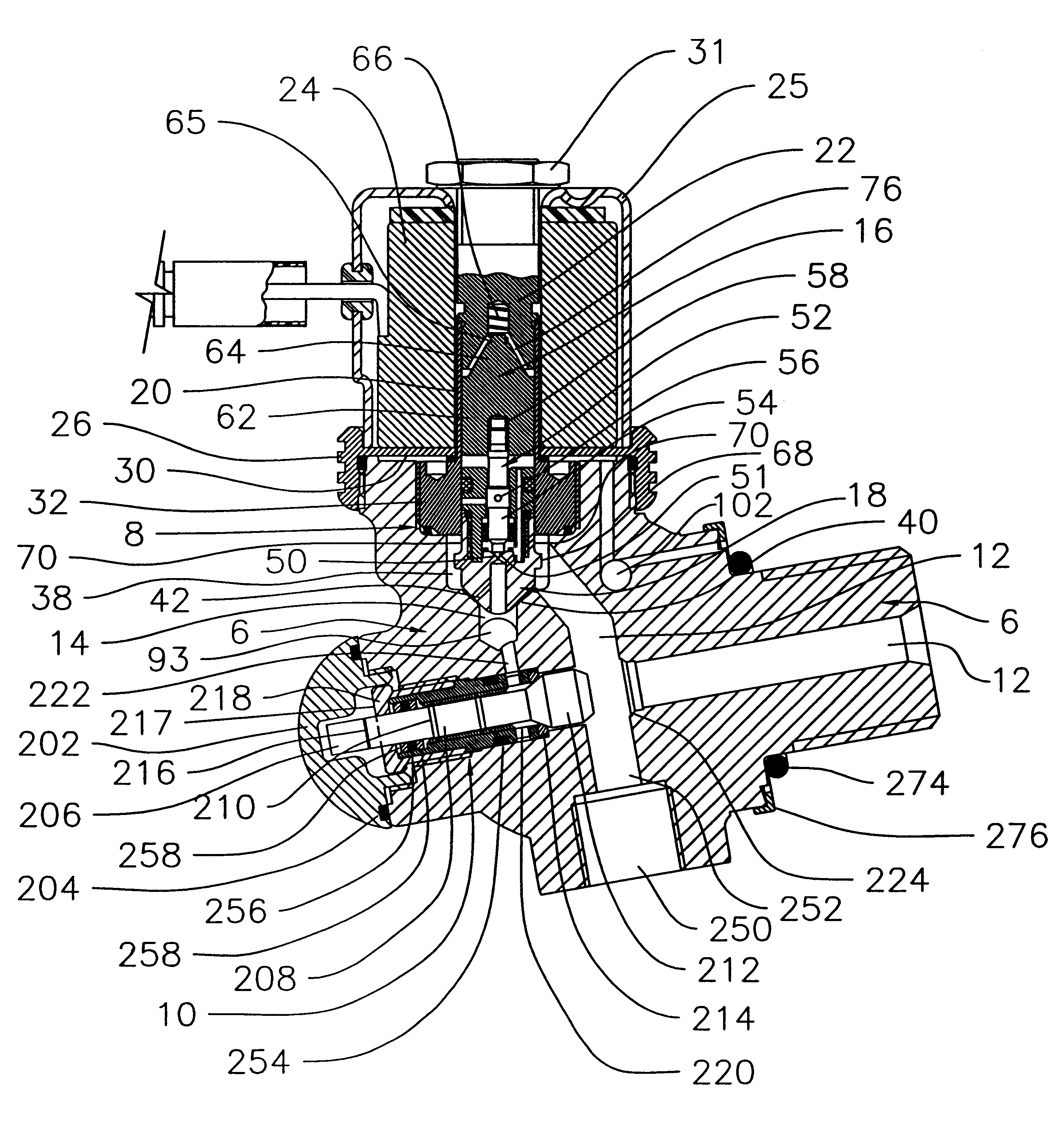
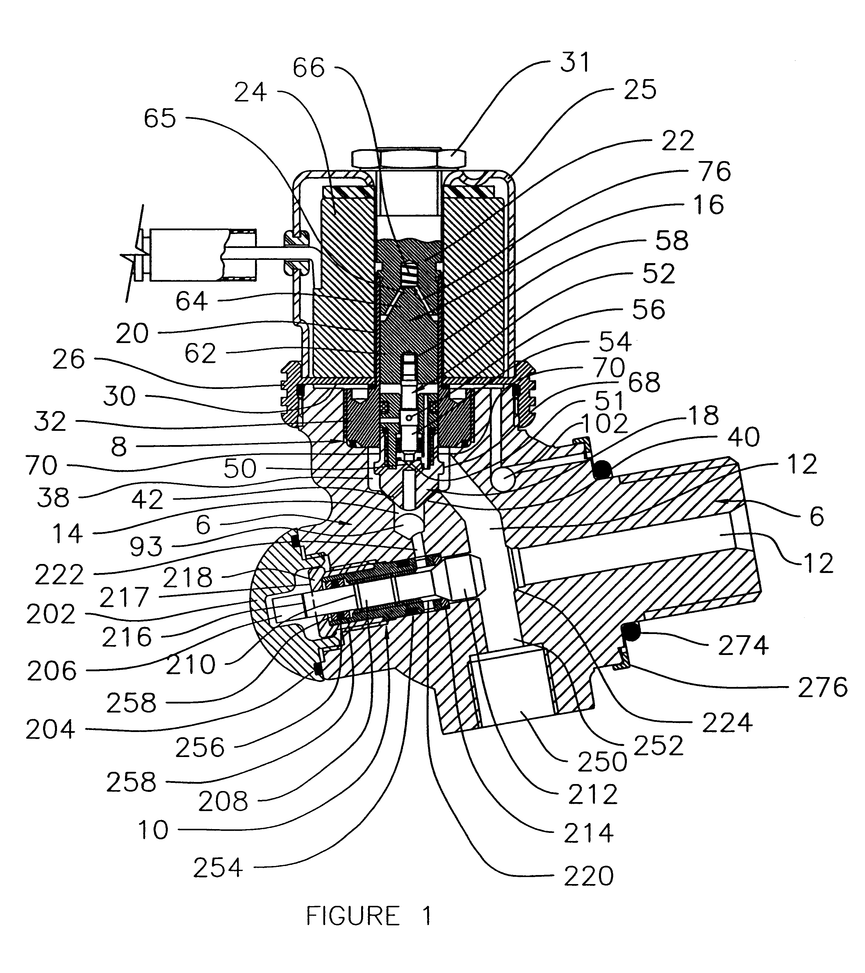
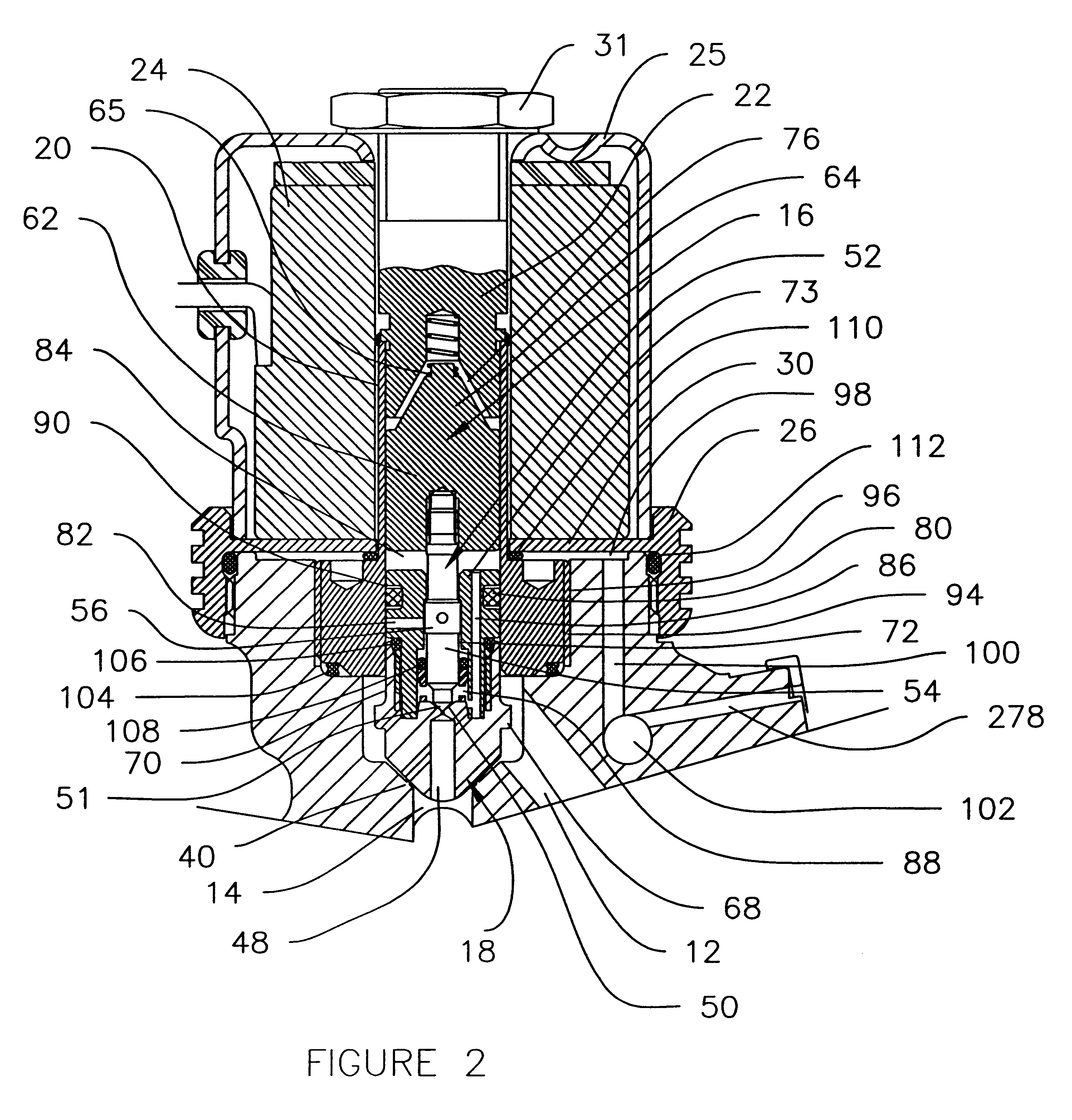
In FIGS. 1, 2 and 3 there is shown a main valve body 6 in section having an instant-on valve 8 and a manual override 10. Drilled into the main body 6 are an inlet passageway 12 and an outlet passageway 14. The drawing illustrates a primary plunger 16 and a secondary piston 18 which are slidably connected to one another in a manner to be described below and which are slidable within a sleeve 20 secured to a stop block 22, with a solenoid coil 24 of conventional construction being mounted about the combination of the sleeve 20 and the stop block 22. The solenoid coil 24 is located within a cover 25. Immediately below the solenoid coil 24 and firmly supporting the same, is a collar 26 having an internal thread which engages a suitable external thread on the main body 6 and which has an integral flange 30 extending inwardly to a location adjacent the sleeve 20. A nut 31 holds the cover 25 in the position shown in the drawing. The material of the collar 26 is ferro-magnetic, with the res...


PUM


Abstract

An instant-on valve assembly with manual override is designed to be connected to a tank containing high pressure gaseous fuel. The valve assembly and manual override allows the tank to be alternately closed off, vented or allows the gas in the tank to bypass the instant-on valve. The instant-on valve assembly can be repaired or replaced without venting the tank. The instant-on valve assembly has a main valve and a bleed valve The main valve has a secondary plunger that opens and closes a main orifice. The bleed valve has a bleed valve stem that opens and closes a bleed orifice. The main valve is slidably mounted within a housing and has a chamber at one end and a zone at another end. Both the zone and the chamber have access to high pressure gaseous fuel within the tank. High pressure gaseous fluid within the zone can be drained when the bleed valve stem is fully open. The bleed valve stem is connected to a solenoid and opens upon activation of the solenoid. When the pressure within the zone is sufficiently reduced, the pressure within the chamber will cause the main valve to open by sliding into the zone. A spring moves the main valve towards a closed position when the solenoid is deactivated. Since the volume of the zone is relatively small, the main valve opens within one second after the solenoid is activated.

Description

1. Field of the InventionThis invention relates to gas valves for use in vehicles powered by natural gas or other gaseous fuels and to a method of operation thereof. Such valves are connected to high pressure tanks that are utilized to open and close a passageway along which high pressure gaseous fuel flows from the tank to an engine of the vehicle in which the system is installed.2. Description of the Prior ArtIt is known to have gas valves installed on high pressure tanks in motor vehicles. Some previous valves are described in U.S. Pat. Nos. 5,193,580; 5,197,710; and 5,341,844 issued to Wass, et al. Since the solenoid on previous valves must overcome the high tank pressure, previous designs utilize a two-stage process in which a small "bleed" orifice is opened initially, the "bleed" orifice being connected to the downstream gas outlet passageway. With time, the pressure in the outlet passageway gradually builds up so that the pressure differential between the tank and the outlet ...

Claims


Application Information

Patent Timeline
Patent Type & Authority Patents(United States)
IPC IPC(8): F16K39/00F16K39/02F16K31/06F16K1/30F16K1/00B60K15/03F02M21/02F02M21/06F16K31/11F17C13/12
CPCF16K1/305F16K1/307F16K31/0655F16K39/024F17C13/123F02M21/0242F02M21/0233Y02T10/32F02M21/0221F02M21/029F17C2201/0109F17C2203/0617F17C2205/0146F17C2205/0332F17C2205/0385F17C2205/0394F17C2221/033F17C2223/0123F17C2260/015F17C2260/036F17C2270/0168Y02T10/30Y10T137/86895Y10T137/87322
Inventor KHADIM, NEIL M.
Owner WESTPORT POWER
Why Eureka
Try Eureka