
Method and apparatus for controlled mixing of fluids

a technology of fluid mixing and control apparatus, which is applied in the direction of lighting and heating apparatus, water supply installation, combustion types, etc., can solve the problems of increasing the severity of flashback, dynamic mixers, and the impracticality of static or dynamic mixers

Inactive Publication Date: 2001-03-20
INST OF GAS TECH
View PDF16 Cites 10 Cited by
  • Summary
  • Abstract
  • Description
  • Claims
  • Application Information

AI Technical Summary

Benefits of technology

It is another object of this invention to provide a method for rapid and intimate mixing of two or more fluids where the fluids to be mixed have substantially different flow rates, which method obviates the need for using carrier fluids and, thus, avoids the need for additional equipment associated therewith.
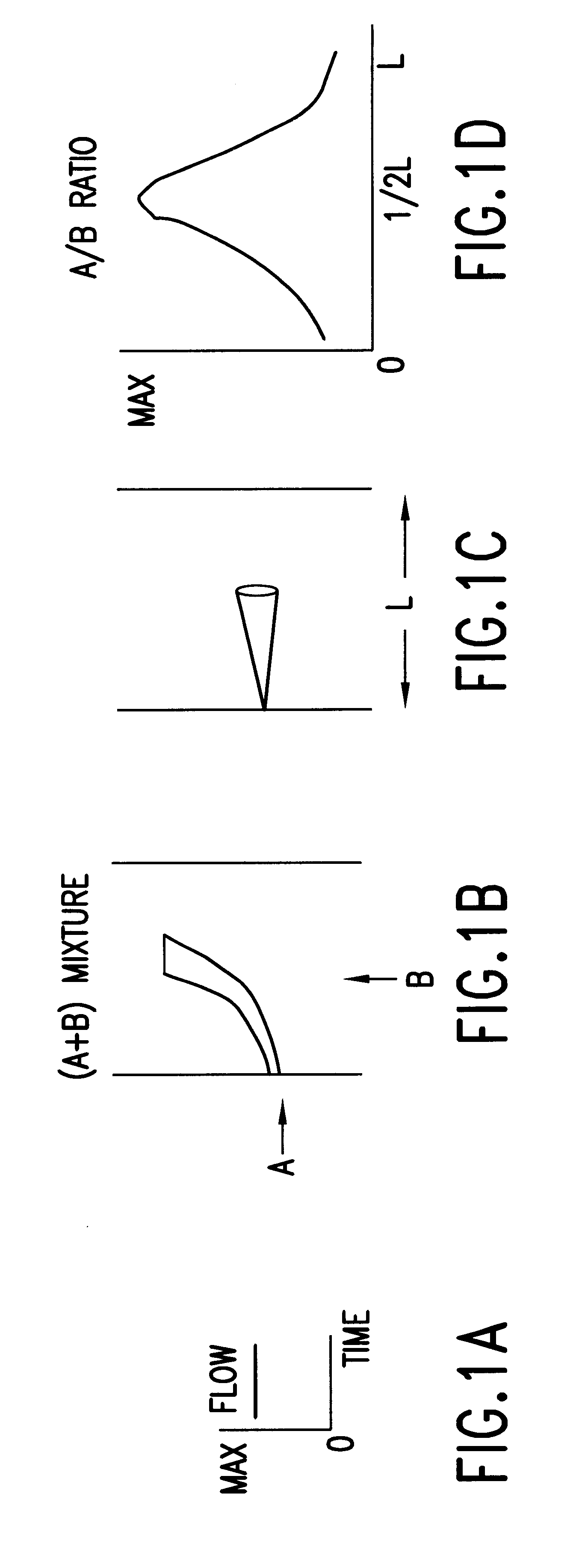
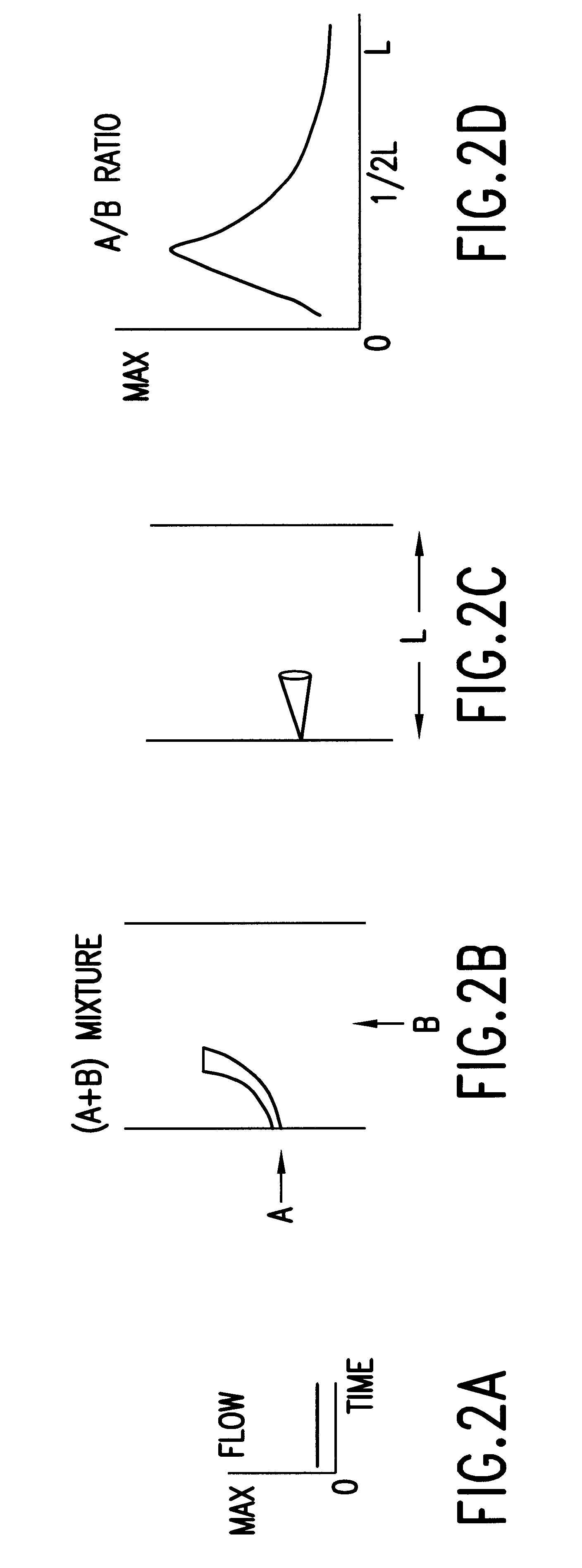
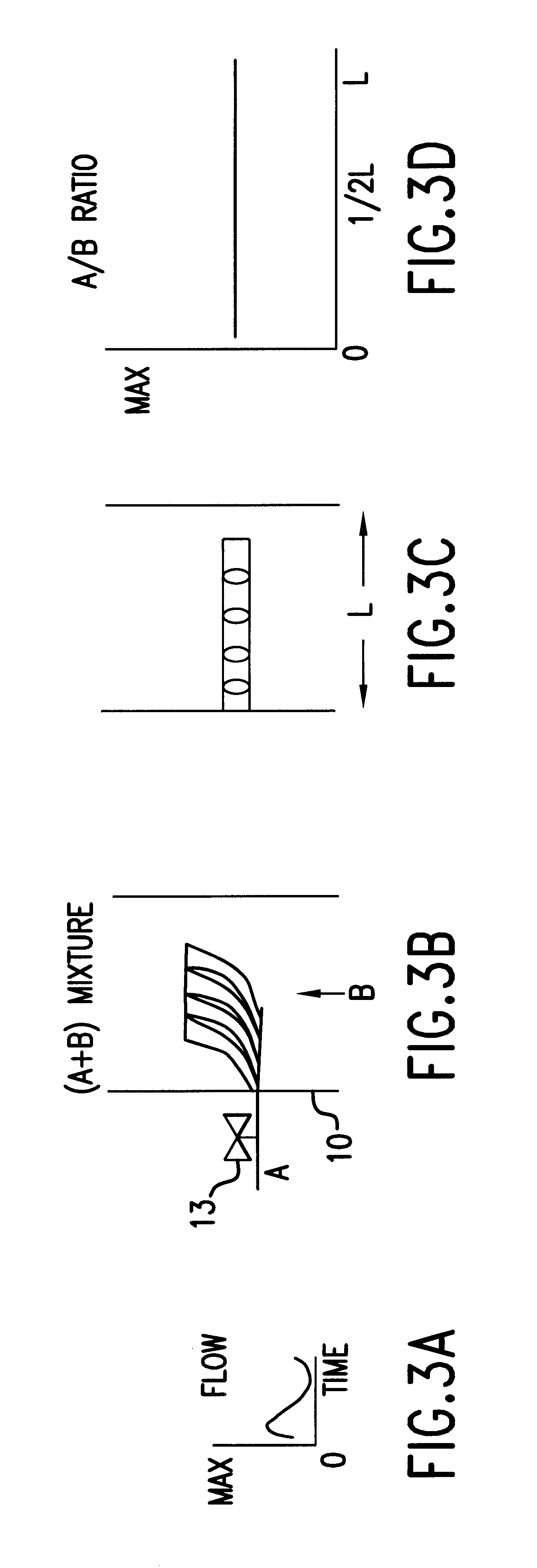
These and other objects of this invention are achieved by a method for mixing fluids comprising the steps of introducing a rapidly continuously variable flow rate stream of a lower flow injection fluid or fluids into a substantially nonvariable (or constant) flow rate stream of a higher flow primary fluid in a direction substantially transverse with respect to the direction of flow of the substantially constant flow rate stream of primary fluid. Rapidly varying the flow rate of the injected fluid or fluids continuously changes the extent of penetration of the injection fluid into the primary fluid stream, creates a controlled profile of mixing, and increases the turbulent mixing of the fluids. This is accomplished by installing any suitable flow control device in the supply line of the injected fluid having the capability of rapidly varying the flow rate of the injected fluid. Such devices include electro-mechanical valves which are operable over a range of openings between fully open and fully closed and the like. One method of controlling the discharge of a fluid is taught, for example, by U.S. Pat. No. 4,176,671 which discloses a valve having a drive element disposed to pinchingly engage a collapsible tube at a high reciprocating speed. A method of discharging slurries by varying valve openings is taught by U.S. Pat. No. 4,257,533, and U.S. Pat. No. 5,500,050 teaches a chemical dispenser controller that automatically learns the chemical feed rate of whatever chemical dispenser it is coupled to and then uses that learned feed rate information to dispense chemicals so as to reach a specified concentration or quantity dispensing target quickly without overshooting the specified target.

Problems solved by technology

In many applications, for example when mixing a solid, liquid or gaseous fuel and an oxidant prior to combustion, or when mixing fuels and / or oxidants with products of partial or complete combustion, static and dynamic mixers are impractical.
In the case of fuel / oxidant mixing prior to combustion, the use of static and dynamic mixers increases the potential for flashback as well as its severity, a highly undesirable consequence.
In the case of mixing fuel and / or oxidant with the combustion products to change the combustion stoichiometry and / or to complete combustion, the use of static or dynamic mixers is also impractical because this requires placement of a relatively large component, namely the in-line mixer, into the combustion products.
In all of these applications, difficulty arises from the need to simultaneously provide both distribution and penetration of the injected fluids so as to provide rapid and uniform mixing.
None of these methods are suitable for selective mixing of fluids, nor are they particularly suitable for applications requiring mixing of two fluids of substantially different flow rates.

Method used


Image

  • Method and apparatus for controlled mixing of fluids
  • Method and apparatus for controlled mixing of fluids
  • Method and apparatus for controlled mixing of fluids

Examples


Embodiment Construction

The method of this invention for mixing fluids comprises the steps of introducing a rapidly varying flow rate stream of an injection fluid into a substantially constant flow rate stream of a primary fluid in a direction substantially transverse with respect to a direction of flow of the substantially constant flow rate primary fluid stream. The method can be used to vary the penetration of the injection fluid jets, to create a controlled spatial and / or temporal profile of mixing, and to increase the turbulent mixing. This is accomplished by installing in the supply line of the injection fluid any suitable device having the ability to rapidly vary the flow rate of the injection fluid. Thus, for the same time averaged flow rate, when the flow control device is open to the maximum degree, the injection fluid is injected at a higher velocity (momentum) than at a steady flow rate, thereby varying both the penetration and the turbulent mixing. The degree of mixing is controlled by changin...


PUM

PropertyMeasurementUnit
flow rateaaaaaaaaaa
frequencyaaaaaaaaaa
degree of mixingaaaaaaaaaa

Abstract

A method for mixing fluids in which a continuously variable flow rate stream of an injection fluid is introduced into a substantially constant flow rate stream of a primary fluid in a direction substantially transverse with respect to the direction of flow of the substantially constant flow rate stream of the primary fluid.

Description

1. Field of the InventionThis invention relates to a method and apparatus for controlled mixing of two or more fluids. More particularly, this invention relates to a method and apparatus for controlled mixing of two or more fluids in which a second fluid stream is introduced into a first fluid stream in a manner which provides rapid and intimate mixing of the fluids or, alternatively, selective mixing of the fluids.2. Description of Prior ArtThere exist many applications which require rapid and intimate mixing of two or more fluids. This is generally accomplished by one or more of the following techniques: (1) using the kinetic energy of the fluids to force the mixing; (2) use of a static mixer installed in the mixture flow stream; and (3) use of a dynamic mixer installed in the mixture flow stream. A wide variety of both static and dynamic types of mixtures are available on the market. Kinetic mixing is generally accomplished by injecting a continuous lower flow rate fluid into a c...

Claims


Application Information

Patent Timeline
Patent Type & Authority Patents(United States)
IPC IPC(8): B01F15/04B01F3/08F23D14/46F23D14/62F23L7/00B01F5/02
CPCB01F3/0865B01F15/0412F23D14/62F23L7/00F23L2900/07003Y10T137/0329B01F23/451B01F35/83
Inventor ABBASI, HAMID ALIRABOVITSER, IOSIF KHAIMWAGNER, JOHN CHARLES
Owner INST OF GAS TECH
Learn More