Catadioptric lens system for collecting and directing light from large aperture luminescent light illuminating fixtures

a technology of dioptric lens and luminescent light, which is applied in the field of luminescent illumination systems, can solve the problems of unacceptably large aperture and frustrating efforts to direct and shape the emitted ligh

Inactive Publication Date: 2001-03-27
COSTA PAUL D
View PDF5 Cites 37 Cited by
  • Summary
  • Abstract
  • Description
  • Claims
  • Application Information

AI Technical Summary

Problems solved by technology

As noted in U.S. Pat. No. 5,235,497, luminescent lighting fixtures have relatively large light apertures that generally frustrate efforts to direct and shape the emitted light.
Even with the geometry for shaping the light from sustained luminescent lighting fixtures as disclosed in U.S. Pat. No. 5,235,497, the apertures can be unacceptably large, particularly when appropriate variations of shadows, and areas of differing luminosity, b

Method used


Image

  • Catadioptric lens system for collecting and directing light from large aperture luminescent light illuminating fixtures
  • Catadioptric lens system for collecting and directing light from large aperture luminescent light illuminating fixtures
  • Catadioptric lens system for collecting and directing light from large aperture luminescent light illuminating fixtures

Examples


Embodiment Construction

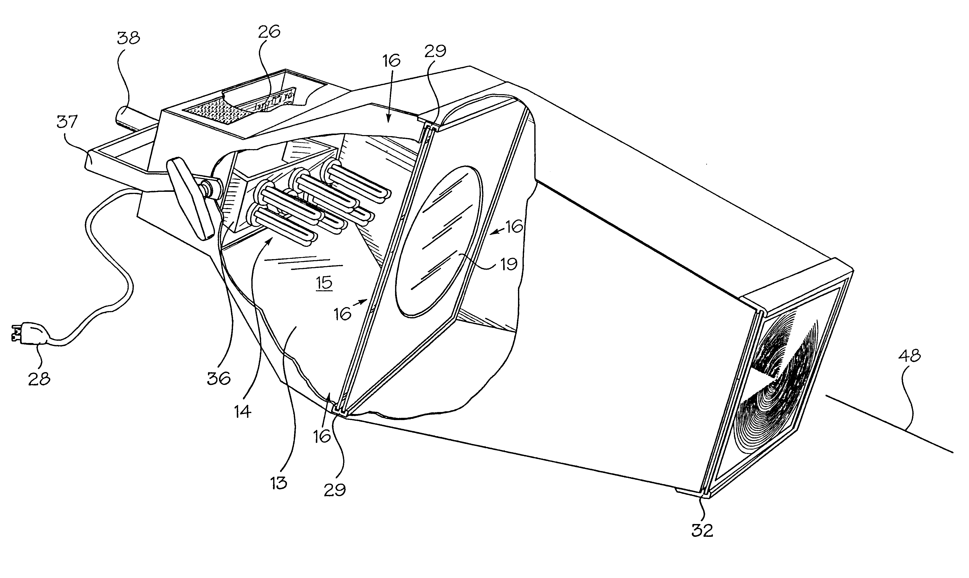
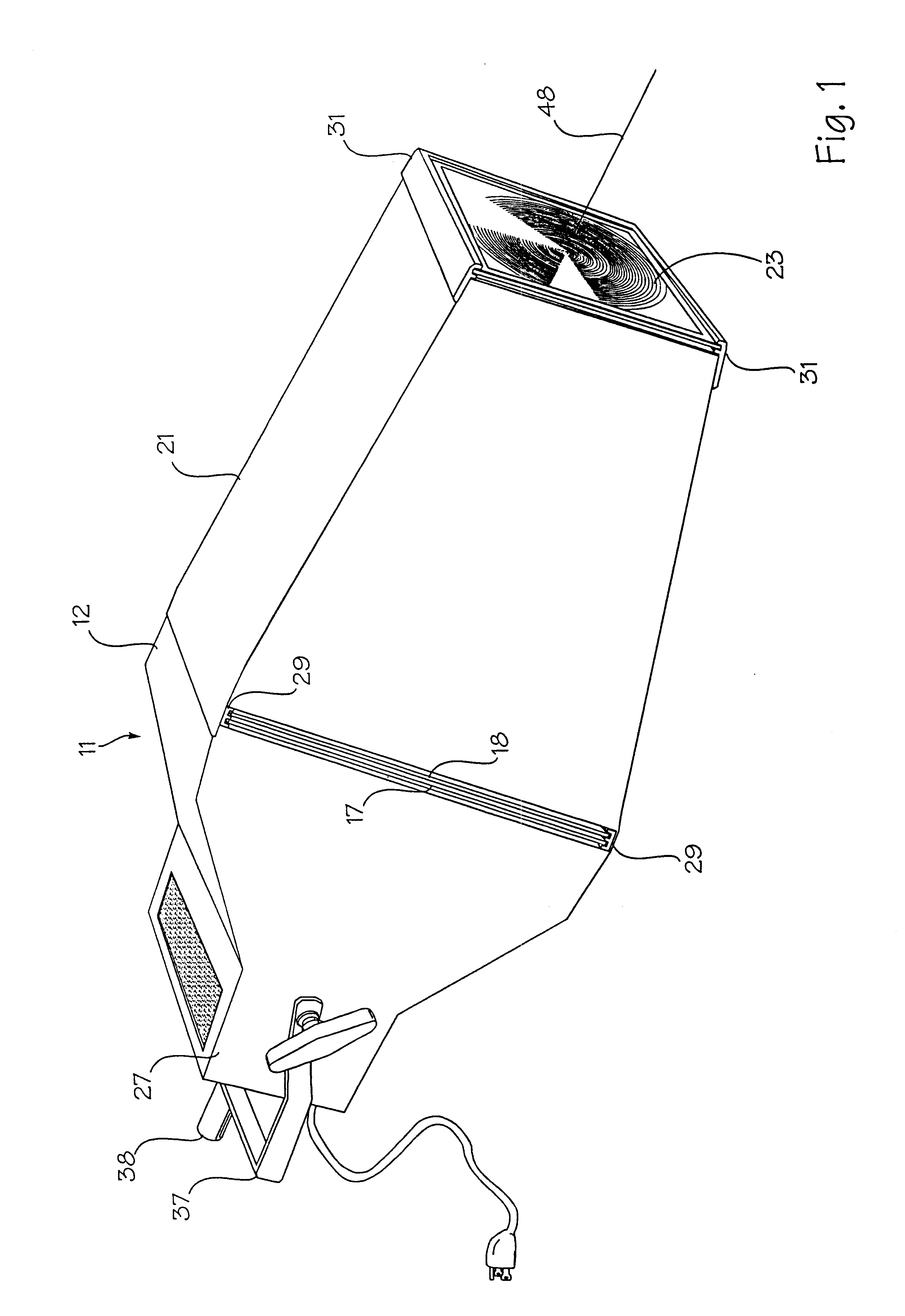
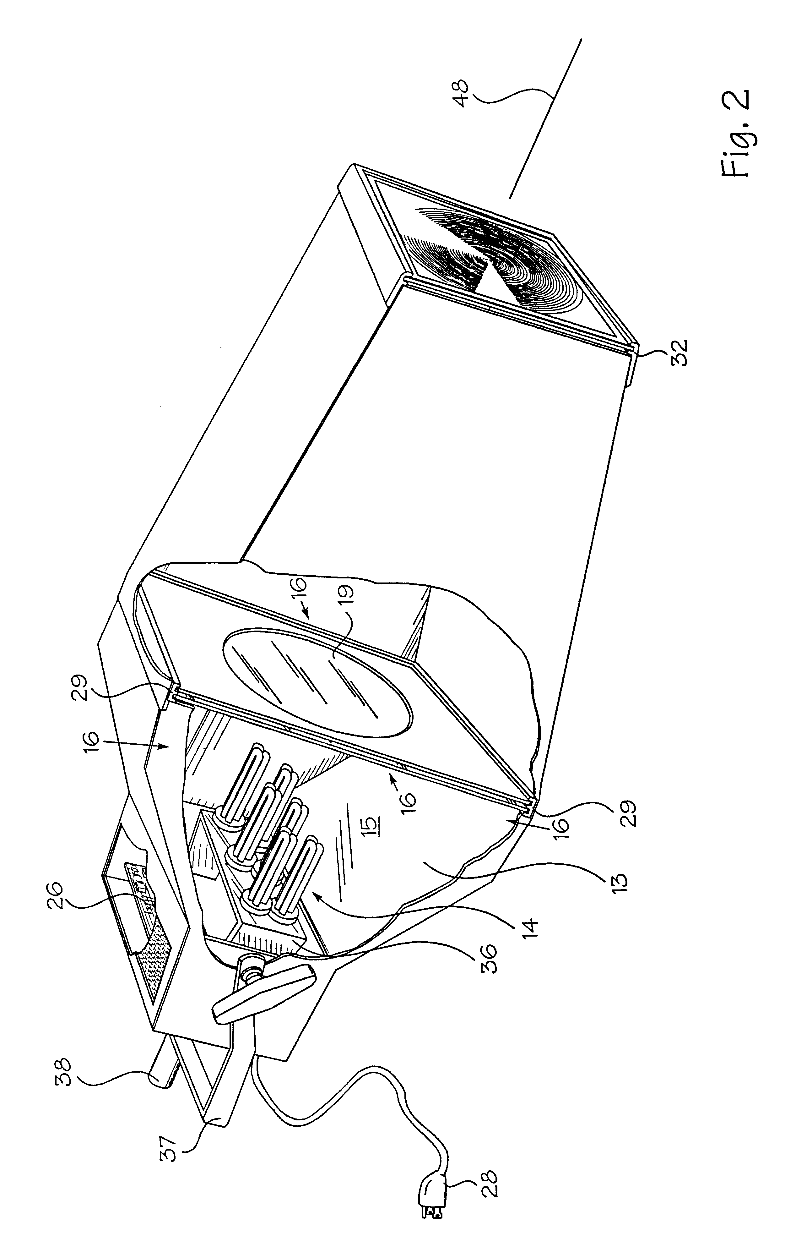
Looking at FIGS. 1 through 4, the invented projection illumination fixture 11 includes a reflector housing 12 with internally supported reflecting surfaces 13 defining a trapezoidal hexahedron light cavity volume 15 directing light emitted by a plurality of trichromatic luminescent light tubes 14 toward a reflector cavity aperture 16 at its base. A transmissive catadioptric lens 17 is disposed across the reflector cavity aperture 16 for optically collecting the light dispersively radiating toward the cavity aperture and converting it into a more-or-less or directed "divergent" light beam. A gobo 18 with a pre-selected shaped aperture 19 is located immediately outward from the catadioptric lens 17 for shaping the cross section configuration of the directed light beam from the catadioptric lens 17. A light snoot or barrel 21 secured to the reflector housing 12 tapers to a second rectangular snoot aperture 22 slightly smaller than the reflector cavity aperture 16. A projection lens 23,...


PUM


Abstract

A projection illumination fixture includes luminescent light tubes lined with an emulsion coating of titanium dioxide and phosphors for producing an appropriate mixture of highly scattered red, blue and green wavelengths of sustained luminescent light emission, a reflector housing for reflecting scattered rays of emitted luminescent light toward an aperture, a catadioptric lens for collecting and redirecting luminescent light rays reaching the aperture into and through a light snoot or barrel and a large area projection (magnifying) Fresnel lens at the end of the light snoot or barrel for directing and spreading the emitted light to fill an illumination field with directional divergent light ideal for dimensionally "painting' talent and objects positioned and moving within the illumination field.

Description

1. Field of the InventionThe invention relates to luminescent illumination systems for television, video and film sets and studios.2. Description of the Prior ArtIn U.S. Pat. Nos. 5,012,396 and 5,235,497 the Applicant, Paul D. Costa describes luminescent lighting fixtures and illumination systems providing omni-directional sustained luminescent (florescent and phosphorescent) light emission of desired color / chromaticity from phosphors in an emulsion coating the interiors of luminescent light tubes for television and film studios.It is important to understand that there are both prompt or fluorescent and delayed or phosphorescent luminescent light emissions excited from the phosphors lining the light tubes. The prompt or fluorescent light emission begins within 10 nsec (10.sup.-9 sec.) of the exciting stimulus and ceases within 10 nsec after excitation stops. The delayed or phosphorescent light emissions can begin after 10 nsec of the exciting stimulus but persists beyond 10 nsec onc...

Claims


Application Information

Patent Timeline
IPC IPC(8): F21V9/10F21V5/00F21V5/04F21V3/00F21V3/04F21V9/00F21S8/00G02B17/08F21V9/40F21V21/30
CPCF21V3/04F21V5/04F21V9/10G02B19/0047G02B19/0028F21V21/30F21W2131/406F21V9/40
Inventor COSTA, PAUL D.
Owner COSTA PAUL D
Why Eureka
Try Eureka