

Method and apparatus for removing air locks within manually operated micro-filtration devices
a technology of micro-filtration device and air lock, which is applied in the direction of hair combs, special dispensing means, water/sewage treatment, etc., can solve the problem that hand-held filtering devices cannot be desirabl
- Summary
- Abstract
- Description
- Claims
- Application Information
AI Technical Summary
Benefits of technology
Problems solved by technology
Method used
Image

Examples
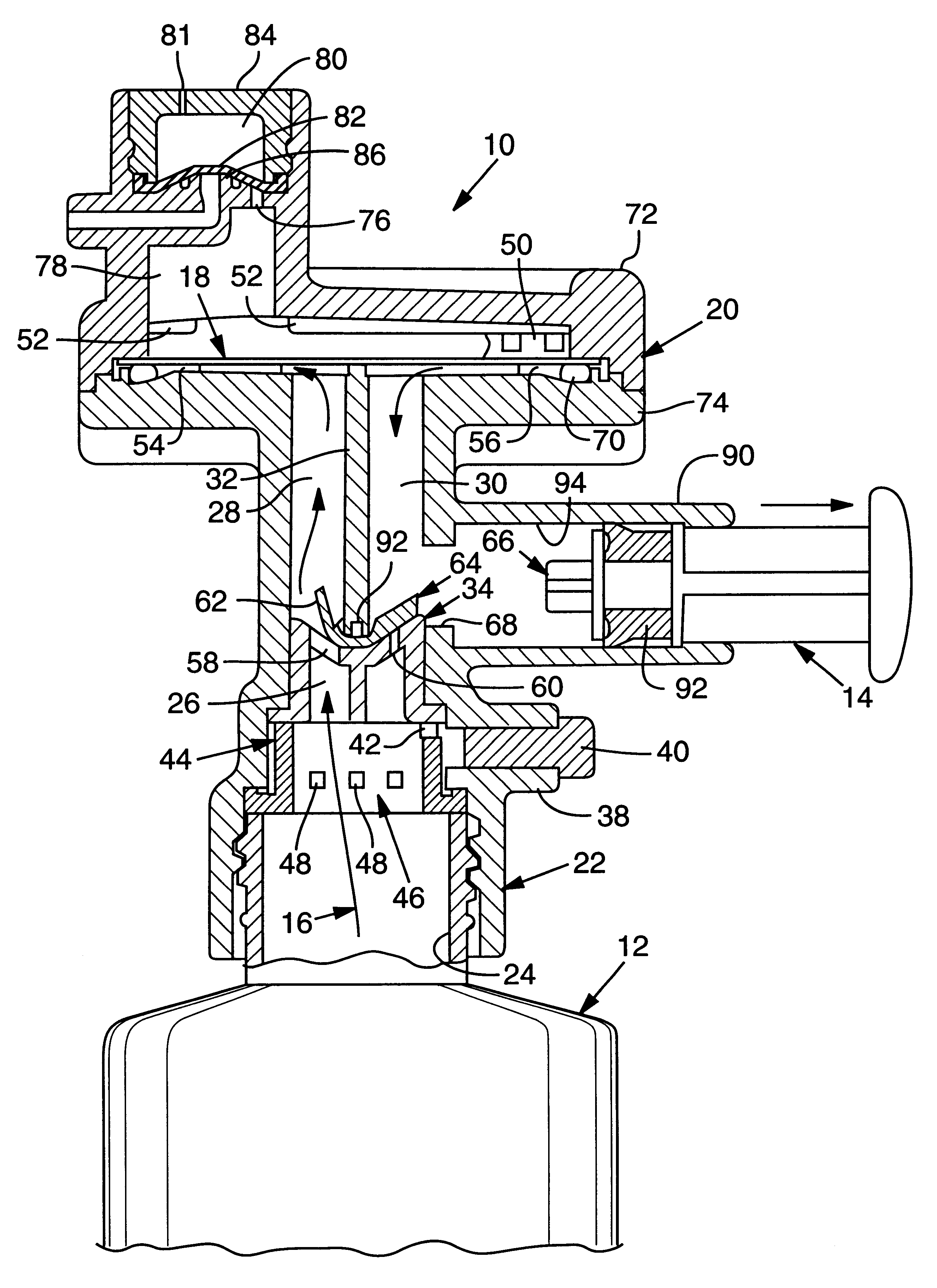
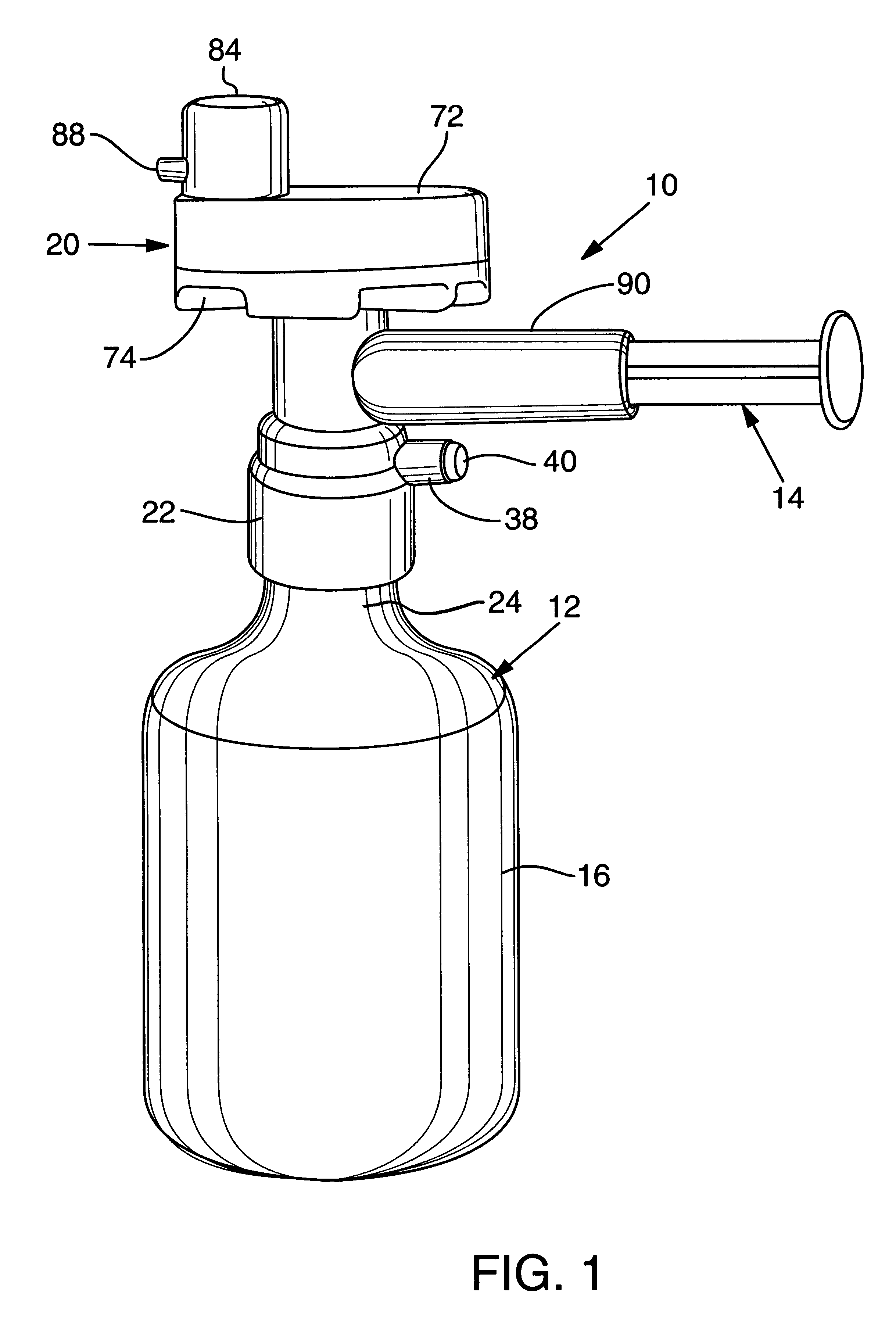
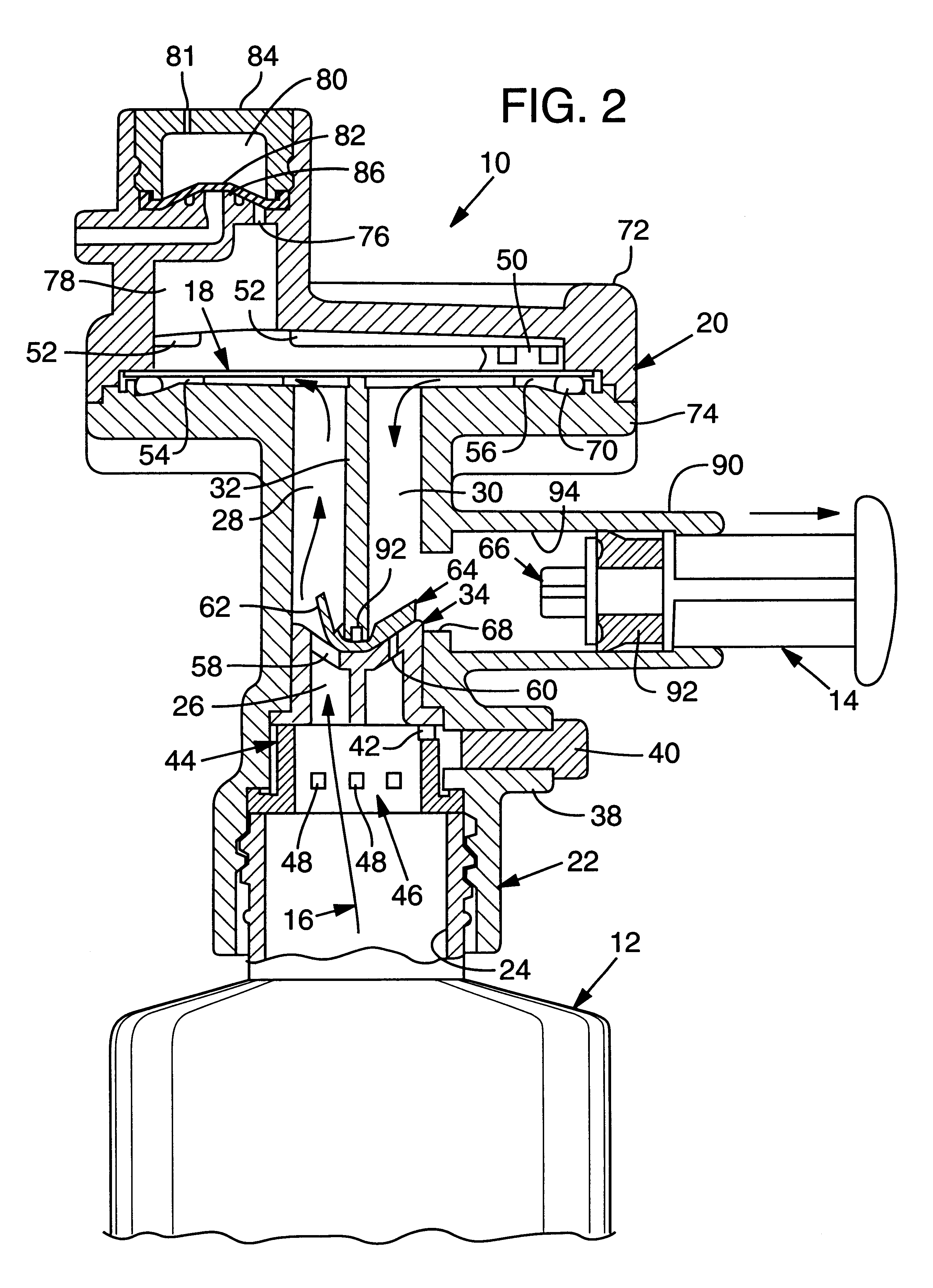
first embodiment
A second embodiment of the device 100 is shown in FIG. 3. In this embodiment chamber 28 is collapsed to negligible height. The piston 138 applies pressure to chamber 216 which communicates with chamber 215. Protuberance 208 presses down on control arm 207 to lift one end of the valve 209 and open channel 149 at the end of the piston's stroke. A feed tube 194 is provided in this embodiment (the first embodiment would require tilting of the bottle to supply liquid to chamber 26). O-ring 115, filter support 193 (the filter is not shown), chamber 112, passage 116, valve 118 and passage 120 in upper housing 110 function as in the previous embodiment. Flap valve 107 operates to open and close passage 148 to permit the flow of saline 192.
third embodiment
the device is shown as 300 in FIGS. 7 through 16. In this embodiment, a filter assembly 302 is threaded onto the threaded neck 303 of hollow storage container 304. The filter assembly 302 comprises a threaded housing 306, and the filter unit assembly 308. The filter unit assembly is shown in more detail in FIG. 10. It comprises the filter unit 310 and cap 312 which is secured to the filter unit 310 by friction fitting of three posts 314 into corresponding receiving tubes (not shown) on the underside of cap 312. A nozzle tube 316 is secured to the outlet channel 318 of filter unit 310. The main nozzle 320, shown from the rear in FIG. 10A, extends through opening 311 in cap 312. It has a cylinder 322 extending from the rear surface, shown in dotted outline in FIG. 10B, with a central bore 323 which is mounted on, and slides on, the central cylinder 317 of nozzle tube 316. Outlet port 324 communicates with the central bore 323 of cylinder 322 and thereby with the nozzle tube 316. The u...
PUM
| Property | Measurement | Unit |
|---|---|---|
| Pressure | aaaaa | aaaaa |
| Diameter | aaaaa | aaaaa |
Abstract
Description
Claims
Application Information