Apparatus for cutting and/or welding flexible packaging

a flexible packaging and welding technology, applied in the direction of laser beam welding apparatus, feeding apparatus of wrapping materials, external support, etc., can solve the problems of substrate sticking to sealing/cutting equipment, requiring mechanical contact between the substrate to be welded and the cutting equipment, and the mechanical complexity of known methods and apparatus

Inactive Publication Date: 2001-03-27
KENDALL BRIAN ANDREW
View PDF12 Cites 52 Cited by
  • Summary
  • Abstract
  • Description
  • Claims
  • Application Information

AI Technical Summary

Benefits of technology

Preferably, the control means may enable variable control of the rate of scanning such that the cuts / welds may be straight or curved.

Problems solved by technology

All three of these methods have the disadvantage of requiring mechanical contact between the substrate to be welded and the cutting equipment.
Mechanical contact can result in substrate sticking to the sealing / cutting equipment, and requires blades or the like which need regular sharpening, replacement, cleaning and maintenance.
These known methods and apparatus are also mechanically complex.
Furthermore, machinery employing these methods requires a stop / start cycle, the stop component necessary to allow time for the mechanical contact between the welding head and the substrate to produce the required weld.
The requirement for multiple welding heads further adds to the mechanical complexity of the equipment.
Another difficulty associated with existing equipment employing welding heads is that some plastics materials are difficult to seal, and it may be impractical to weld thick gauge substrates, to weld plastic to metal foil, or to weld temperature-resistant materials.
Moreover, with hot metal, radio frequency and ultrasonic welding the focusing of heat may be poorly controlled making it difficult to weld or seal shrink film, for example.
In addition, these conventional systems may require ramping in of dwell time and preheating of sealing mechanisms which add to their complexity.
If they don't have such features then there are inefficiencies associated with scrap substrate.
However, where such laser technology has been employed it has not generally been adapted for use in association with highspeed packaging machinery, In particular, the laser beams have been fixed, for the production of welds, seals or score lines in a longitudinal direction along a moving film, or means of lateral scanning have been inefficient, of limited lateral span and / or not designed for use with continuously moving webs or films of material.

Method used


Image

  • Apparatus for cutting and/or welding flexible packaging
  • Apparatus for cutting and/or welding flexible packaging

Examples


Embodiment Construction

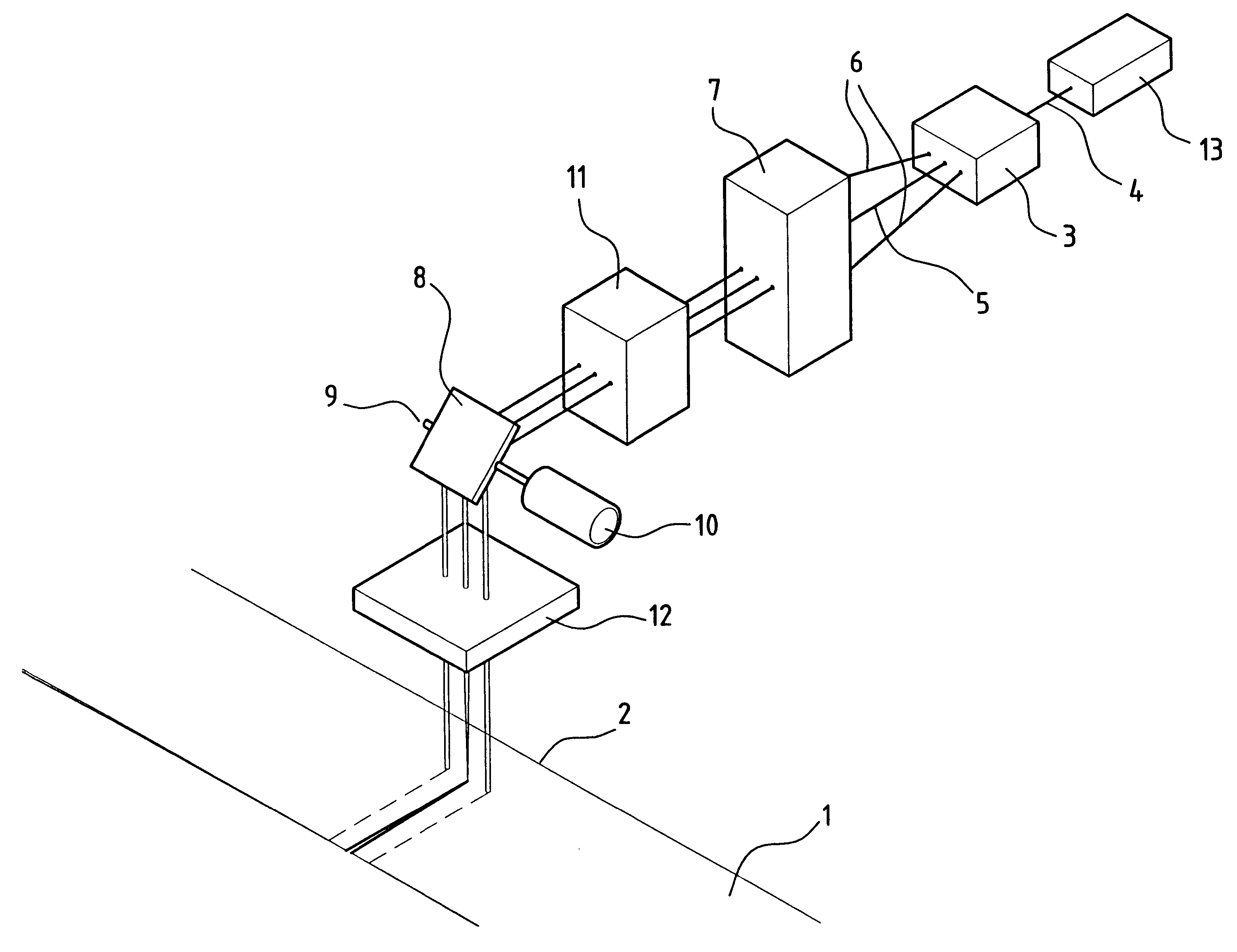
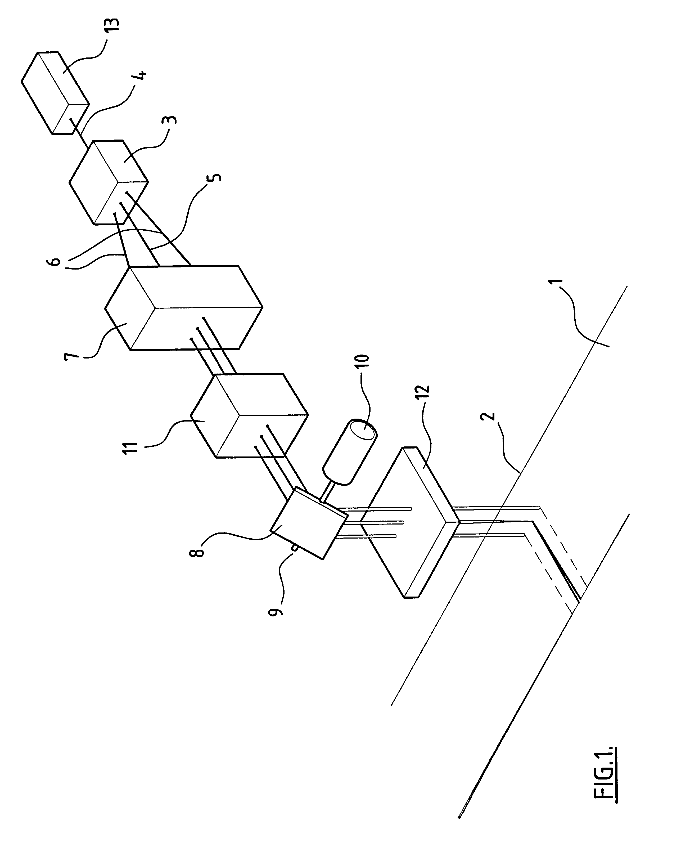
The method and apparatus of the present invention are targeted primarily at the packaging industry for welding thermoplastic films such as polyethylene, polypropylene, polyamides, polycarbonate, ethylene-vinylacetate, polyester, polyvinyl chlorides, ethylene-vinylalcohol and surlyn, and foil and other such materials. Apparatus of the present invention includes a means of transporting two or more layers of a plastics material, forming the substrate 1, to a welding / cutting or operational site 2, at which site optically controlled laser beams are employed to perform the operational task required. The transportation is in the manner of a continuous feed.

At the welding / cutting site 2 means are provided for bringing the two or more films or webs of material into intimate contact with each other. This may be by any known means, including, for example, by projecting compressed air onto the substrate to force the layers together against a support, by having the films or webs pass over a tens...


PUM

PropertyMeasurementUnit
angleaaaaaaaaaa
flexibleaaaaaaaaaa
power densityaaaaaaaaaa

Abstract

This invention involves a method and apparatus for welding and/or cutting flexible packaging material (1) using lasers. The invention is specifically directed towards the use of lasers for cutting and/or welding plastics material (1) in motion, such as in association with high speed packaging machinery. The method and apparatus of the invention enables the cutting and/or welding of adjacent webs of plastics material (1) by scanning one or more processing laser beams (4), or sub-beams (5, 6) of the or each processing laser beam (4), across said moving layers (1) at a rate controlled in relation to the rate of motion of the layers (1) of substrate. The method and apparatus may produce straight or shaped cuts and/or welds.

Description

This invention relates to a method and apparatus for welding and / or cutting flexible packaging material using lasers.Welding and cutting of plastics film or foil is particularly important with flexible packaging equipment, for example in the bag making industry, and also in form / fill / seal machinery.There are three main methods for welding plastics film or foil utilised in packaging machinery. These are hot metal welding, radio frequency welding and ultrasonic welding.All three of these methods have the disadvantage of requiring mechanical contact between the substrate to be welded and the cutting equipment. Mechanical contact can result in substrate sticking to the sealing / cutting equipment, and requires blades or the like which need regular sharpening, replacement, cleaning and maintenance. These known methods and apparatus are also mechanically complex.Furthermore, machinery employing these methods requires a stop / start cycle, the stop component necessary to allow time for the mec...

Claims


Application Information

Patent Timeline
Patent Type & Authority Patents(United States)
IPC IPC(8): B23K26/06B23K26/067B23K26/08B29C65/14B29C65/00B29C65/16
CPCB23K26/067B23K26/0676B23K26/0846B23K26/206B29C65/1654B29C65/1664B29C65/7473B29C66/024B29C66/1122B29C66/232B29C66/43B29C66/8266B29K2101/12B29K2077/00B29K2069/00B29K2067/00B29K2031/04B29K2029/00B29K2027/06B29C65/1619B29C65/76B29C65/7852B29C66/0242B29C66/934B29C66/98B29C2793/0045B29K2023/06B29K2023/12B29C65/00B29C65/1658B29C66/71B29C66/73921B29K2023/086B29K2023/083
Inventor KENDALL, BRIAN ANDREW
Owner KENDALL BRIAN ANDREW
Why Eureka
Try Eureka