Internal clock jitter detector

a technology of internal clock and detector, which is applied in the direction of pulse generator, pulse manipulation, pulse technique, etc., can solve the problems of inherently variable internal clock in a microprocessor, shrinking of the clock cycle which limits critical paths, and uncertainty in phase time affecting half-cycle paths

Inactive Publication Date: 2001-03-27
INTEL CORP
View PDF1 Cites 40 Cited by
  • Summary
  • Abstract
  • Description
  • Claims
  • Application Information

AI Technical Summary

Problems solved by technology

The instability of the internal clock of a microprocessor can cause numerous problems.
For example, uncertainty in the ideal period duration can result in temporal clock cycle shrink which limits critical paths.
Furthermore, uncertainty in phase time can affect half-cycle paths.
These problems are attributable to clock jitter, which is caused and exacerbated by various factors.
For example, the internal clock in a microprocessor is inherently subject to variation caused by power supply noise modulating the delay of the clock distribution network.
The systematic accumulated / response error from the PLL / clock generator further increases the uncertainty of the clock edge.
Measurement of on-chip jitter is hampered by flip-chip packages that are difficult to probe.
Clock jitter can be driven off chip via buffers, but the buffers are also subject to the same delay variations that cause the clock jitter.
Because on-chip jitter is purely internal to a chip and chips are becoming more complex, this type of jitter is becoming more difficult to observe accurately with existing devices and techniques.

Method used


Image

  • Internal clock jitter detector
  • Internal clock jitter detector
  • Internal clock jitter detector

Examples


Embodiment Construction

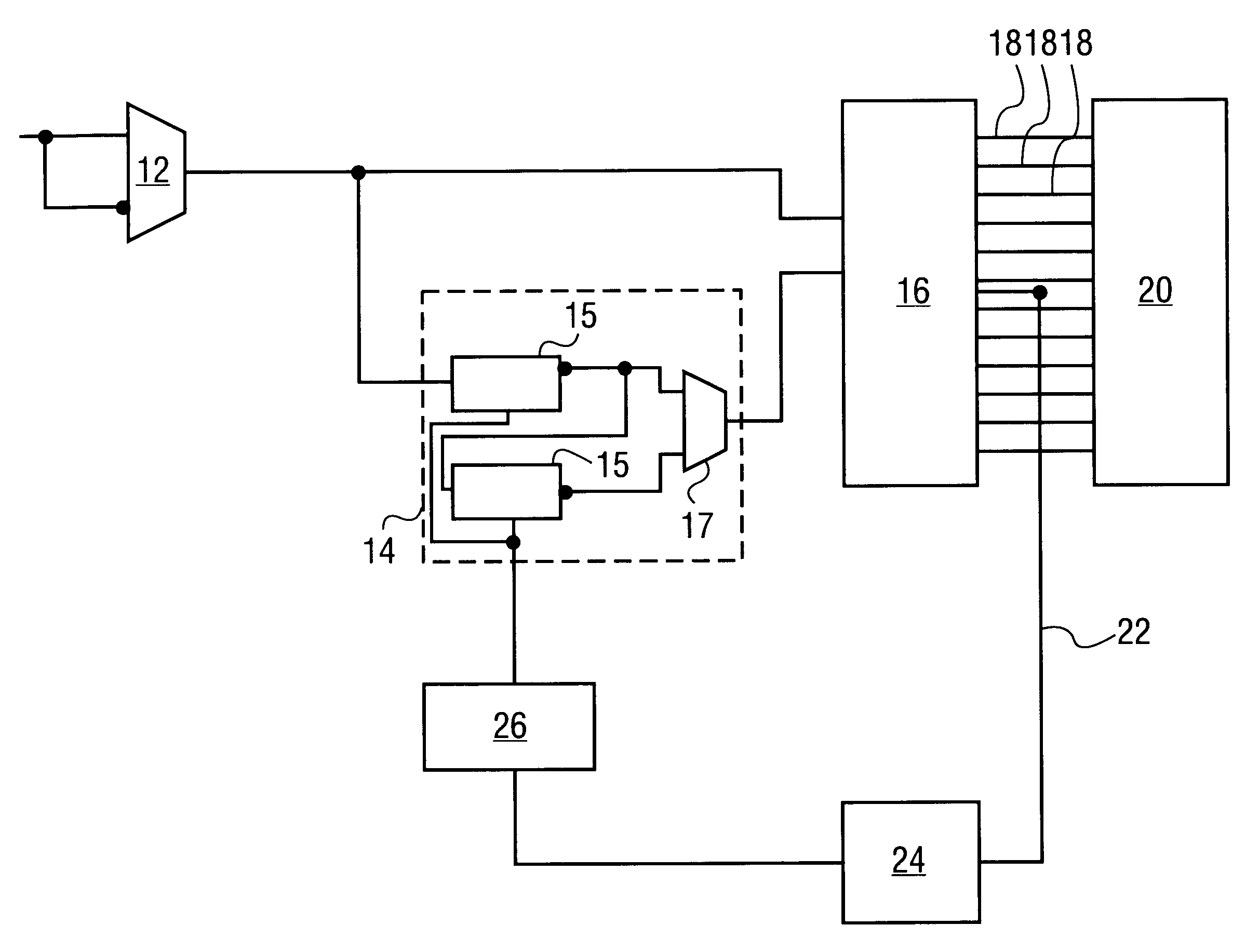
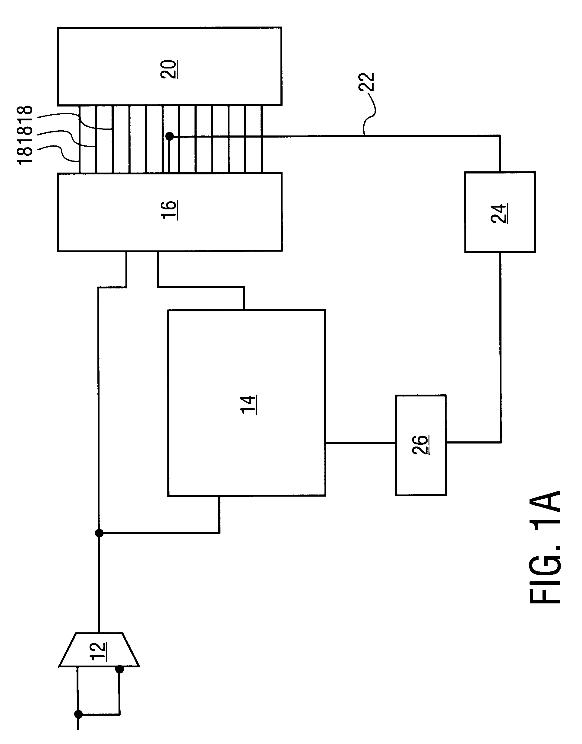
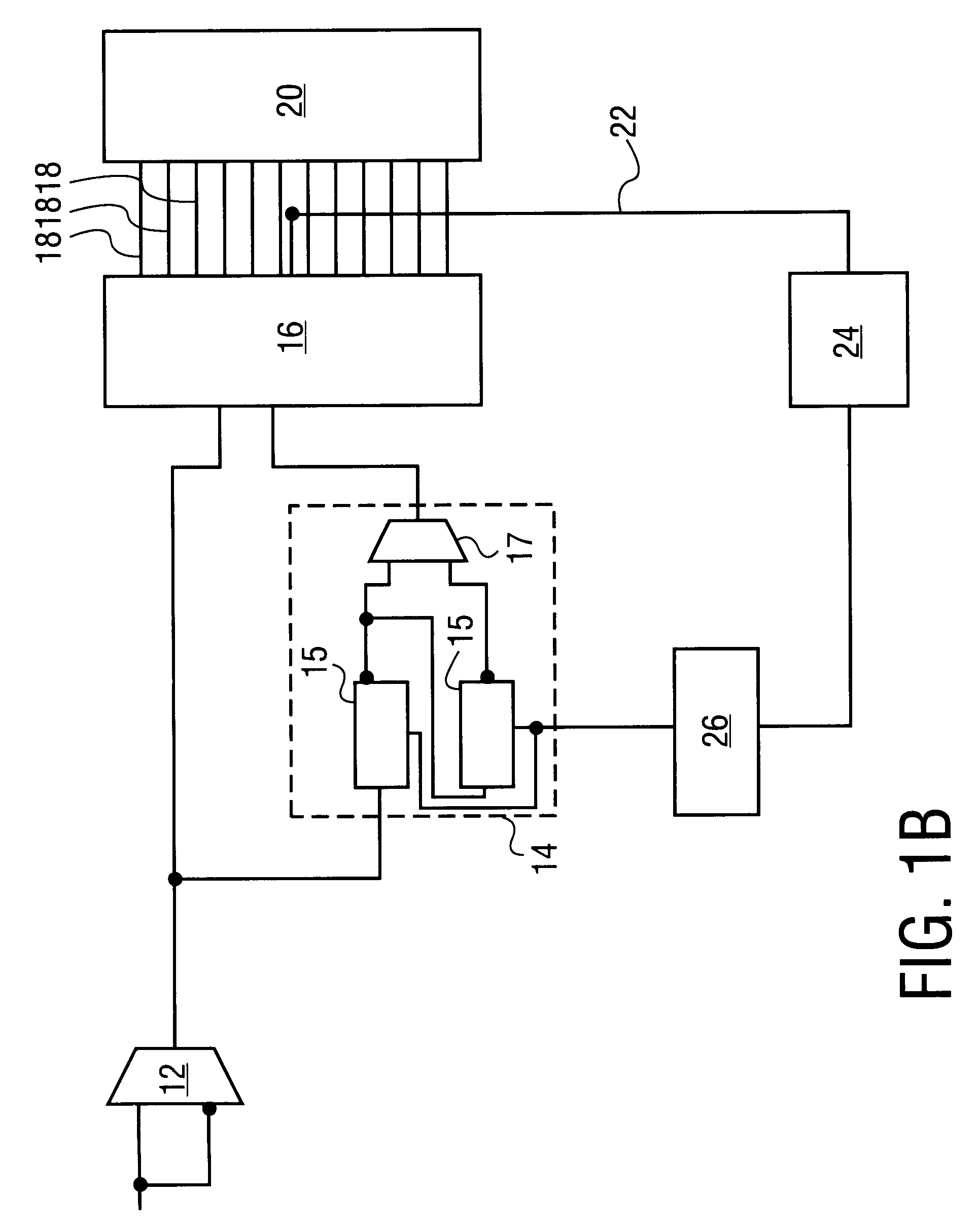
An apparatus and method for detecting and measuring internal clock jitter is disclosed. The following description provides embodiments of the present invention. However, it will be appreciated that other embodiments of the present invention will become apparent to those of ordinary skill in the art upon examination of this description. Thus, the present description and accompanying drawings are for purposes of illustration and are not to be used to construe the invention in a restrictive manner.

In one embodiment of the present invention, a reference clock generator receives a clock signal and generates a reference clock signal based on the clock signal. The reference clock signal includes the clock signal delayed for an average duration. A phase comparing element receives and compares the clock signal and the reference clock signal. A phase difference between the clock signal and the reference clock signal is indicated in one of a number of phase difference bins. Each phase differen...


PUM


Abstract

An apparatus and method for detecting and measuring internal clock jitter is disclosed. In one embodiment, a reference clock generator generates a reference clock signal based on an instantaneous clock signal. The reference clock signal includes the instantaneous clock signal delayed for an average duration. A phase comparing element receives both the instantaneous clock signal and the reference clock signal such that the phase comparing element measures a phase difference between the instantaneous clock signal and the reference clock signal. The magnitude and direction of the phase difference is indicated by one of a number of distinct phase difference bins in the phase comparing element.

Description

BACKGROUND OF THE INVENTION1. Field of the InventionThe present invention relates generally to microprocessor circuits, and more specifically to internal clocks in microprocessor circuits.2. Background InformationThe instability of the internal clock of a microprocessor can cause numerous problems. For example, uncertainty in the ideal period duration can result in temporal clock cycle shrink which limits critical paths. Furthermore, uncertainty in phase time can affect half-cycle paths. As the speeds of microprocessors increase, these types of problems take on greater significance.These problems are attributable to clock jitter, which is caused and exacerbated by various factors. For example, the internal clock in a microprocessor is inherently subject to variation caused by power supply noise modulating the delay of the clock distribution network. The systematic accumulated / response error from the PLL / clock generator further increases the uncertainty of the clock edge.As the inter...

Claims


Application Information

Patent Timeline
Patent Type & Authority Patents(United States)
IPC IPC(8): H03L7/091H03L7/081H03L7/08
CPCH03L7/0814H03L7/091H03L7/0816
Inventor WONG, KENG L.TAYLOR, GREGORY F.KUPPUSWAMY, RAVISHANKARPARKER, DOUGLAS R.MA, HUNG-PIAOCALLAHAN, KENT R.DAI, XIA
Owner INTEL CORP
Why Eureka
Try Eureka