Optical pulse source

a pulse source and optical technology, applied in the field of optical pulse sources, can solve the problems of performance limitations, previously proposed direct modulated sources cannot operate beyond 40 gbit/s, and high operating costs

Inactive Publication Date: 2001-03-27
IPG PHOTONICS CORP
View PDF5 Cites 22 Cited by
  • Summary
  • Abstract
  • Description
  • Claims
  • Application Information

AI Technical Summary

Problems solved by technology

Operation at such rates places heavy demands on the optical sources used.
By contrast, previously proposed directly modulated sources have not been capable of operation beyond 40 Gbit/s.
This system improv...

Method used


Image

  • Optical pulse source
  • Optical pulse source
  • Optical pulse source

Examples


Embodiment Construction

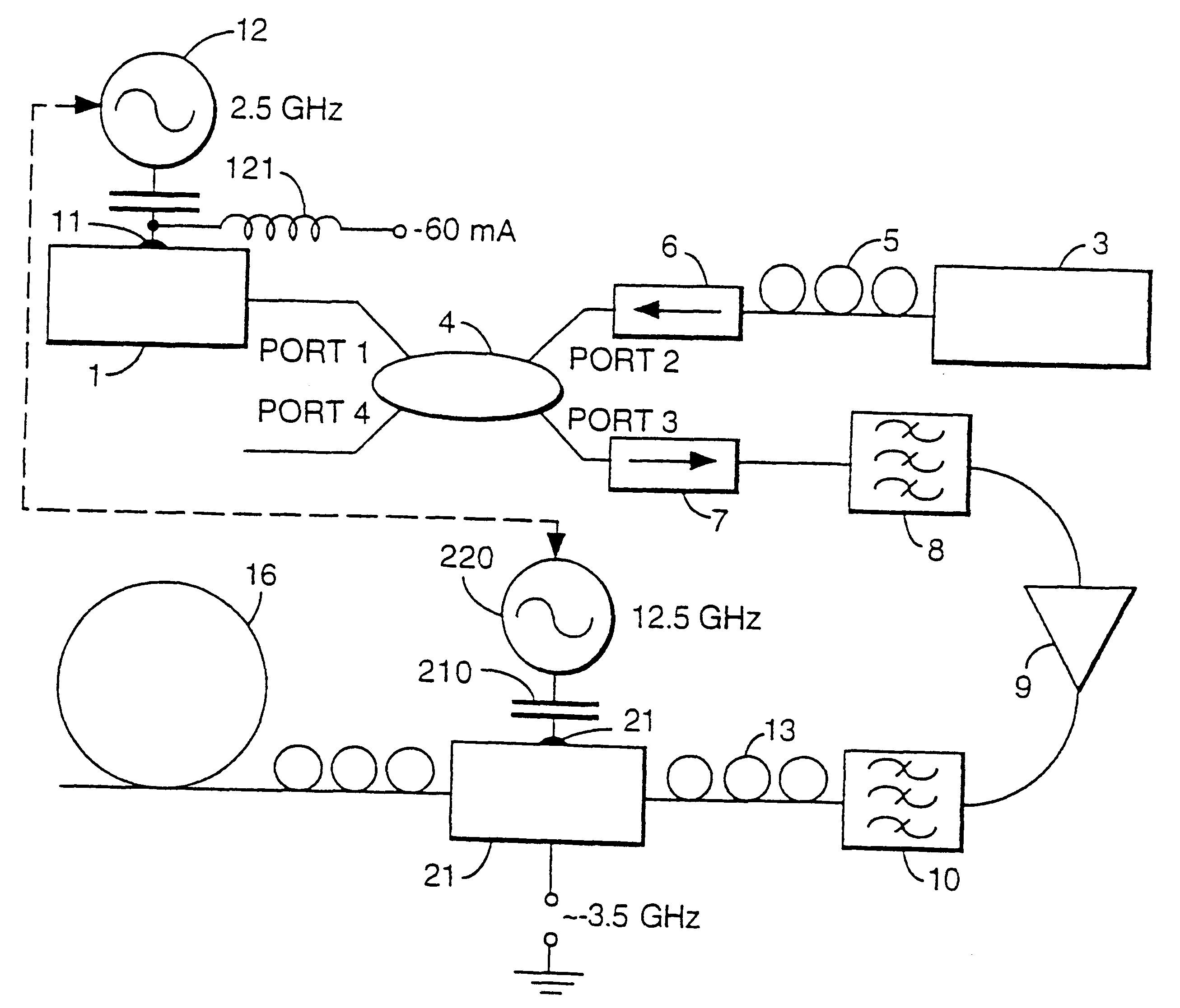
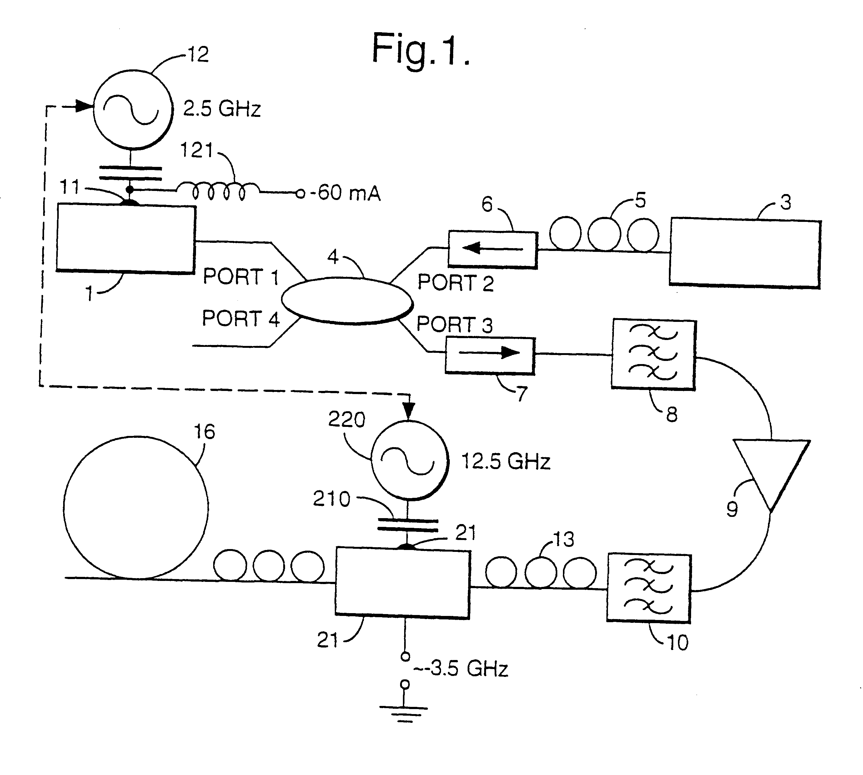
An optical pulse source comprises a gain-switched distributed feedback semiconductor laser diode (DFB-SLD) 1 and an electro-absorption modulator (EAM) 21 connected to the optical output of the DFB-SLD. Light from a cw source 3 is coupled into the optical cavity of the DFB-SLD via a 50:50 coupler 4. The DFB-SLD 1 and modulator 21 are driven via their respective gates 11, 20 by electrically phased-locked RF sources 12,220. The optical components are connected together by lengths of optical fibre 5, and polarisation controllers PC are associated with the fibre at the output of the cw source 3, and on either side of the EAM 21.

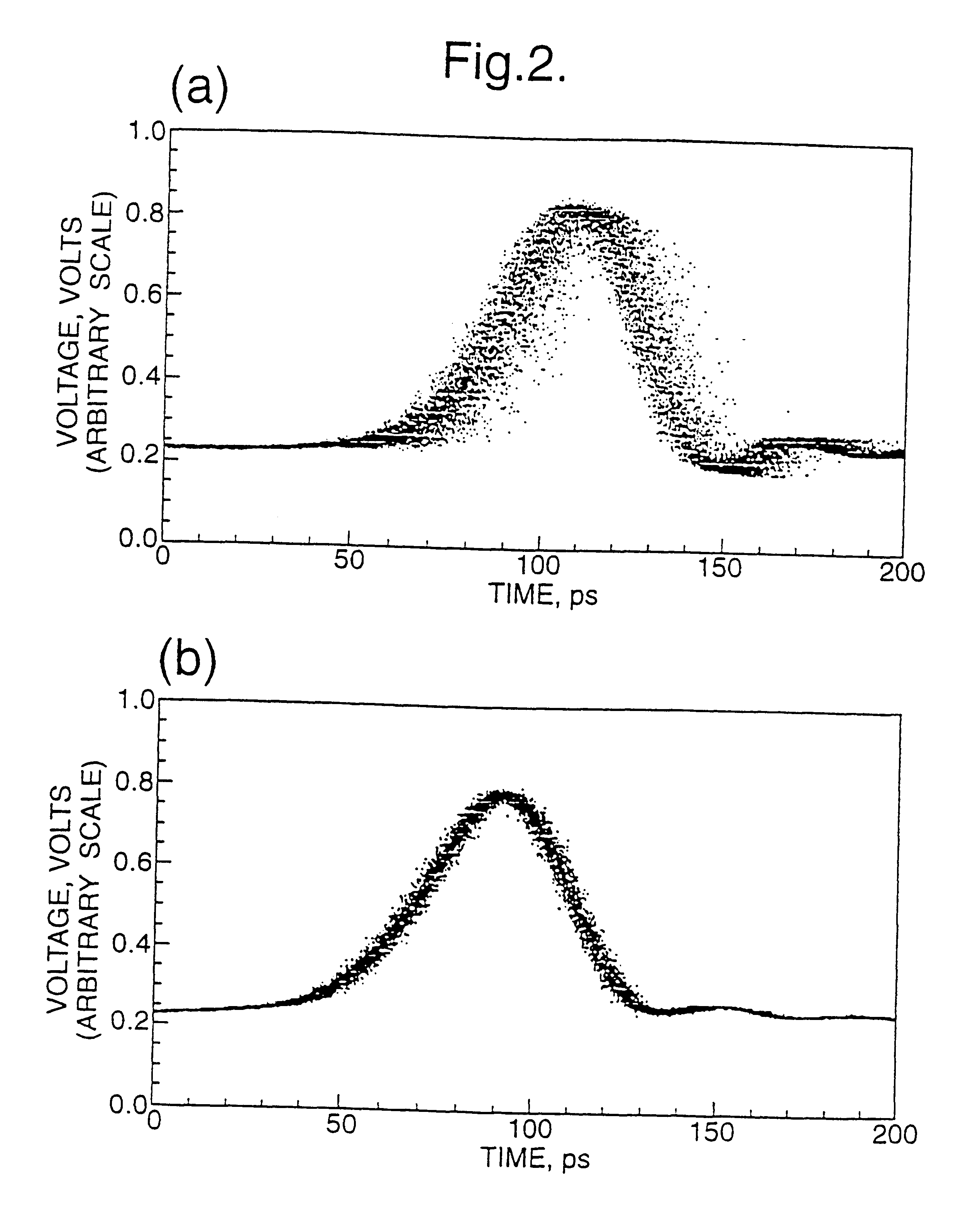
In this first example, the frequency of the RF drive for the SLD 1 is 2.5 GHz, while the frequency of the drive applied to the EAM is five times that at 12.5 GHz. It is the frequency of the RF drive to the SLD which determines the pulse repetition rate: a higher frequency is used for the EAM in order that the drive signal should be sufficiently sharp. The output o...


PUM


Abstract

An optical pulse source includes a gain-switched semiconductor laser diode. Light from a continuous wave source is opitically coupled into the laser cavity. Light output from the laser cavity passes through an electro-optic amplitude modulator. Synchronized modulating signals are applied to the semiconductor diode and to the amplitude modulator. The source outputs short low-jitter low-pedestal optical pulses and is suitable for use, for example, in a broadband optical network operating at thigh bit rates of 100 Gbit/s or more, or in an optical interconnect.

Description

1. Field of the InventionThe present invention relates to an optical pulse source. Such a source might be used, for example, in a transmitter for a broadband optical network or in an optical interconnect.2. Related ArtBroadband optical networks are expected to operate at data transmission rates of 100 Gbit / s and beyond. Operation at such rates places heavy demands on the optical sources used. The repetition rate required of the pulse source may be less than the full bit rate, since the datastream at the full bit rate will typically be generated by multiplexing the optical source in the time domain. However, for this to be possible, the pulses output by the source need to be of short duration and desirably should have low temporal jitter.According to a first aspect of the present invention there is provided an optical pulse source comprising:a) a gain-switched semiconductor laser diode;b) a continuous wave light source which is coupled to the optical cavity of the semiconductor laser...

Claims


Application Information

Patent Timeline
IPC IPC(8): H01S5/40H04B10/152H04J14/08H04B10/213H04B10/155H01S5/00H04B10/50H04B10/508
CPCH01S5/4006H04B10/505H04B10/508H04J14/08
Inventor GUNNING, PAULSMITH, KEVINRUSSELL, DAVEYLUCEK, JULIAN KAZIMIERZMOODIE, DAVID GRAHAMNESSET, DEREK
Owner IPG PHOTONICS CORP
Why Eureka
Try Eureka