
Automatic gain control method and device

A technology of automatic gain control and gain switching, applied in power management, wireless communication, electrical components, etc., can solve the problems of high cost, performance deterioration, and phase mutation of radio frequency circuits, and achieve the effect of ensuring timeliness and cost, and improving performance.

Active Publication Date: 2013-07-03
SPREADTRUM COMM (SHANGHAI) CO LTD
View PDF7 Cites 12 Cited by
  • Summary
  • Abstract
  • Description
  • Claims
  • Application Information

AI Technical Summary

Problems solved by technology

[0011] Taking the 3GPP LTE system as an example, the shortest CP is only less than 4.7us. Considering the avoidance of the delay extension of the previous symbol and the sample time and processing time of power measurement, the setting and stabilization time left for the radio frequency circuit is even less than 2us. Such a limited RF setup and stabilization times can be extremely costly for RF circuitry, or not possible at all;
[0012] 2. Since different OFDM symbols in the corresponding scheme are set to different gains, different gains may cause phase mutations between different OFDM symbols, seriously deteriorating receiver performance
[0013] Generally, the channel estimation of the OFDM system relies on the reference signals (or reference subcarriers) placed in the specific subcarriers of the symbols according to certain rules. The reference signals are usually distributed among different OFDM symbols. Each reference signal is passed through the time domain / frequency domain Cooperative processing such as interpolation obtains the channel estimation of each symbol and each subcarrier; in the conventional AGC control scheme, the phase mutation will be introduced due to the gain change between different OFDM symbols, and the performance of the aforementioned channel estimation activities will be inevitable due to the cooperation between symbols significantly deteriorated

Method used


Image

  • Automatic gain control method and device
  • Automatic gain control method and device

Examples


Embodiment Construction

[0036] Embodiments of the present invention provide an automatic gain control method and device, which are used to improve the performance of the automatic gain control on the basis of ensuring the timeliness and cost of the automatic gain control.

[0037] In order to make the purpose, features and advantages of the present invention more obvious and understandable, the technical solutions in the embodiments of the present invention will be clearly and completely described below in conjunction with the accompanying drawings in the embodiments of the present invention. Obviously, the following The described embodiments are only some, not all, embodiments of the present invention. All other embodiments obtained by those skilled in the art based on the embodiments of the present invention belong to the protection scope of the present invention.

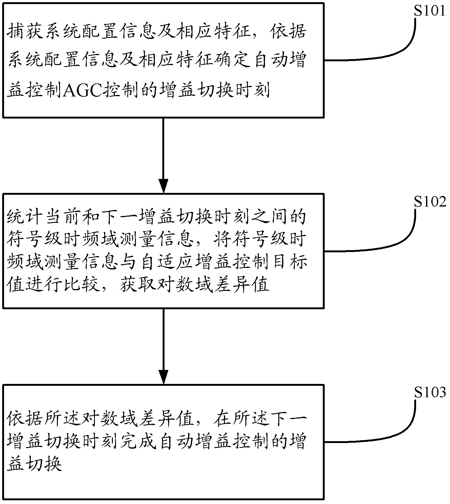
[0038] The automatic gain control method provided by the embodiment of the present invention, such as figure 1 shown, including:

[...


PUM


Abstract

The invention relates to the technical field of mobile communication and discloses an automatic gain control method and a device. On the basis of guaranteeing timeliness and cost of automatic gain control, the automatic gain control method and the device are used for improving performance of the automatic gain control. The automatic gain control method comprises the following steps: capturing system configuration information and corresponding characteristics, determining gain switching time of AGC according to the system configuration information and the corresponding characteristics, counting symbol level time-frequency domain metrical information between the current gain switching time and the next gain switching time, the symbol level time frequency domain metrical information comprises frequency domain power Pw of default resource unit location in various symbols and time domain power Psymbol of the various symbols, comparing the symbol level time frequency domain metrical information with an adaptive gain control target value, obtaining a logarithmic domain difference value, and according to the logarithmic domain difference value, completing gain switching of the automatic gain control at the next gain switching time.

Description

technical field [0001] The present invention relates to the technical field of mobile communication, in particular to an automatic gain control method and device. Background technique [0002] In the mobile communication system, due to the variable physical distance between the two parties, the complexity of the wireless channel, and the change of service life and death, the dynamic range of the signal is usually relatively large. ) system as an example, the standard signal dynamic range is -25dBm ~ -106dBm, and the dynamic span is as high as 81dB. It should be noted that the dynamic range may be even greater in practical applications, and it is generally believed that it can reach a level of about 90-95dB. [0003] In order to cope with the signal reception with a large dynamic range, automatic gain control (AGC for short) technology is widely used. The receiving circuit using this technology adopts a preset method to adjust the amplification factor, amplifies the small-a...

Claims


Application Information

Patent Timeline
IPC IPC(8): H04W52/52
Inventor 谭舒桂竞晶冯侨申敏
Owner SPREADTRUM COMM (SHANGHAI) CO LTD
Learn More