Method and apparatus for fail safe control of an electronically controlled throttle valve of an internal combustion engine

a technology of electronic control and internal combustion engine, which is applied in the direction of electric control, fuel injection control, machines/engines, etc., can solve the problems of acceleration or deceleration, travel cannot be performed, and the accelerator position sensor and the throttle position sensor are likely to fail to opera

Inactive Publication Date: 2001-04-03
UNISIA JECS CORP +1
View PDF11 Cites 34 Cited by
  • Summary
  • Abstract
  • Description
  • Claims
  • Application Information

AI Technical Summary

Problems solved by technology

In case the one sensor fails to operate, if the throttle valve position is controlled using the remaining sensor, there may take place acceleration or deceleration due to the unintended opening/closing operation of the throttle valve in case the remaining sensor also fails to operate.
According to the fail-safe system in the above-mentioned fully electronically-controlled throttle system, however, if the one sensor fails to operate, the throttle valve is forcibly maintained the fail-safe position at least at that moment without utilizing the value detected by the remaining normal sensor, causing such an inconvenience that the travelling can only be performed at, for example, 40 kilometers/hour at the fastest.
Besides, among the parts constituting the electronically-controlled throttle system, the accelerator position sensor and the throttle position sensor are likely to fail to operate.
Either one of the two accelerator position sensors or either one o

Method used


Image

  • Method and apparatus for fail safe control of an electronically controlled throttle valve of an internal combustion engine
  • Method and apparatus for fail safe control of an electronically controlled throttle valve of an internal combustion engine
  • Method and apparatus for fail safe control of an electronically controlled throttle valve of an internal combustion engine

Examples


Embodiment Construction

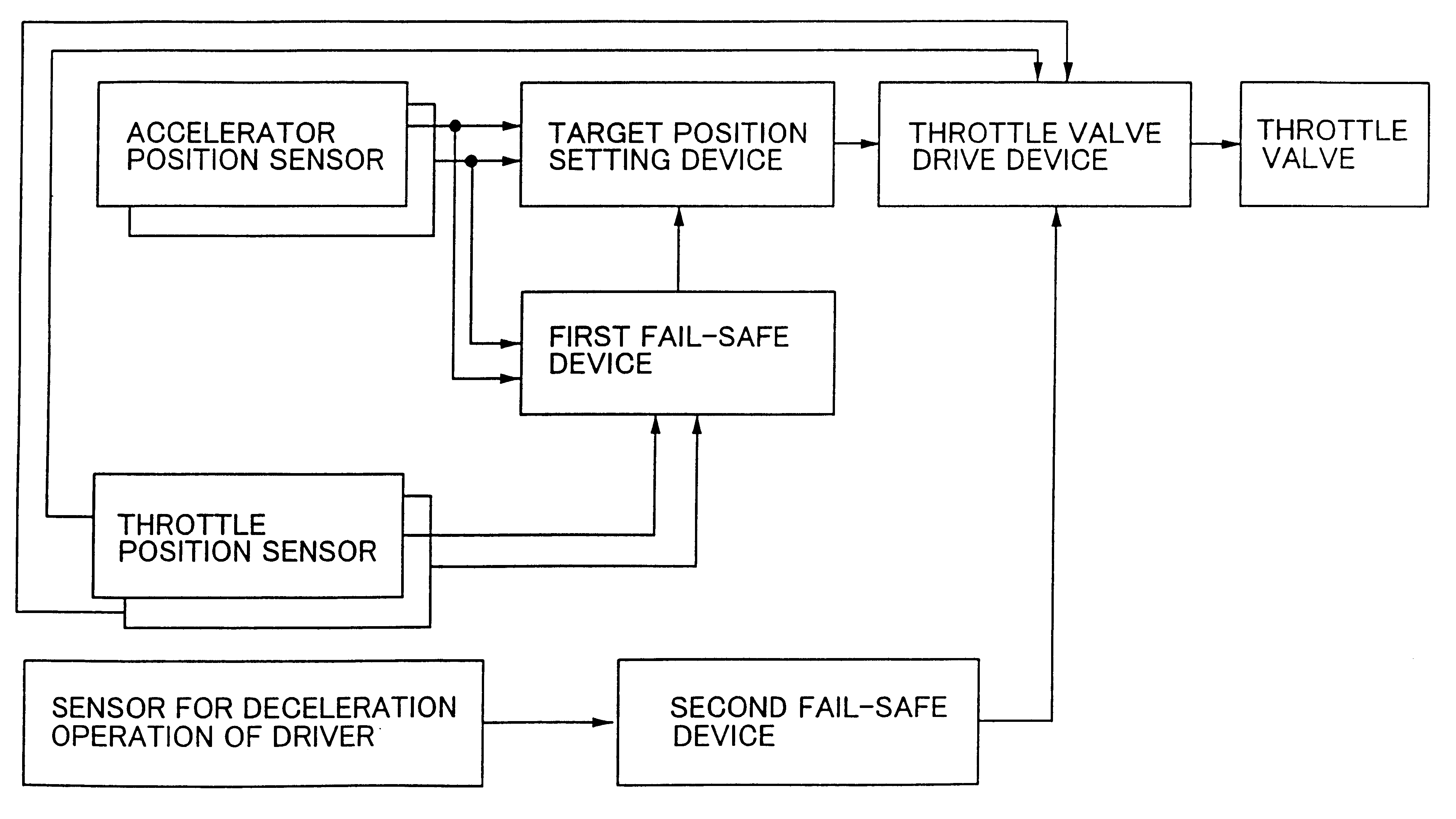
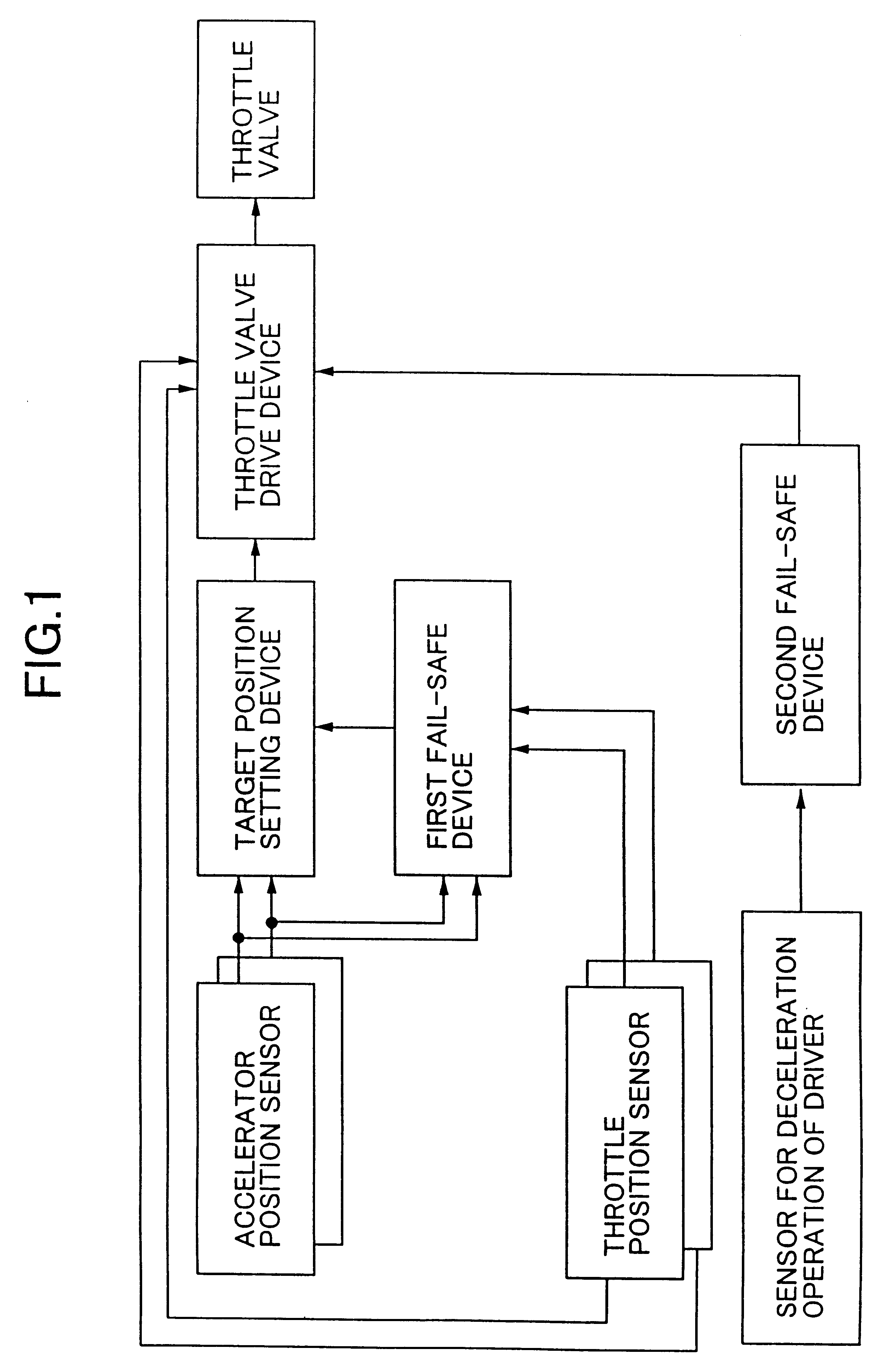
A first apparatus for fail-safe controlling an electronically-controlled throttle-type internal combustion engine according to the present invention comprises devices shown in FIG. 1.

Two accelerator position sensors are provided to detect a position of an accelerator, respectively.

A target position-setting device sets a target position of a throttle valve disposed in an intake system depending upon engine operation conditions inclusive of the position of the accelerator detected by one accelerator position sensor selected from the two accelerator position sensors.

Two throttle position sensors are provided to detect a position of the throttle valve, respectively.

A throttle valve drive device opens and closes the throttle valve by using an actuator, so that the position of the throttle valve detected by one throttle position sensor selected from the two throttle position sensors reaches the target position.

When either one of the two accelerator position sensor or of the throttle posit...


PUM


Abstract

In a method and apparatus for fail-safe controlling an electronically-controlled throttle-type internal combustion engine, provision is made of two accelerator position sensors and two throttle position sensors. When either one of the two accelerator position sensors or either one of the two throttle position sensors fails to operate, a low-speed fail-safe operation of a minimum compensation, that is, an operation for maintaining a minimum output required for limp-home control operation of the engine, is executed and, then, a first fail-safe control operation is executed for controlling the position of the throttle valve using a value detected by the remaining sensor. Therefore, the throttle valve is not unintentionally opened, and the operation can be smoothly shifted to the first fail-safe control operation. When the operation for decelerating the engine is detected by a sensor of a system separate from the above-mentioned sensors, the first fail-safe control operation is interrupted and, instead, a second fail-safe control operation is executed for holding the throttle valve at a predetermined position in order to assure the low-speed fail-safe operation of the minimum compensation.

Description

1. Field of the InventionThe present invention relates to an internal combustion engine equipped with an electronically controlled throttle system opened and closed by an actuator in order to accomplish a target position of the throttle valve disposed in an intake system and, particularly, to fail-safe control technology at a time when the sensors constituting the system become abnormal.2. Related Art of the InventionThere has been proposed an electronically-controlled throttle system for electronically controlling the position of the throttle valve to obtain a target air quantity based on the position of the accelerator (depressed amount of the accelerator pedal) or on the position of the accelerator and the engine rotation speed (see Japanese Unexamined Patent Publication No. 7-180570).Among such electronically controlled throttle systems, in case the drive system fails to operate, those (fully electronically-controlled throttle systems) without a limp-home mechanism for mechanica...

Claims


Application Information

Patent Timeline
IPC IPC(8): F02D11/10
CPCF02D11/107F02D2041/227
Inventor MACHIDA, KENICHIIRIYAMA, MASAHIRONOZAKI, MIKIO
Owner UNISIA JECS CORP
Why Eureka
Try Eureka