Quick-release lock assembly with compression/expansion capability

a technology of quick release and lock assembly, which is applied in the direction of threaded fasteners, transportation and packaging, liquid/gas/vapor treatment of definite length materials, etc., can solve the problems of difficult disengagement of locking assembly, loss of high pressure of dye medium, and simple nut locking members that are impractical

Inactive Publication Date: 2001-04-10
R TEX
View PDF6 Cites 28 Cited by
  • Summary
  • Abstract
  • Description
  • Claims
  • Application Information

AI Technical Summary

Problems solved by technology

Due to shrinkage of the yarn rolls as a result of chemical impregnation and differential temperature effects during the dying operation, simple nut locking members are impractical, since they become loosened in use, and the high pressure of the dye medium is lost as a concomitant of the resulting leakage.
A major problem which has been experienced in the use of such locking assemblies is that they tend to lock or seize in position on the threaded end rod due to the high pressure on the locking assembly exerted in the distal direction of the rod, so that the locking assembly is extremely difficult to disengage when t...

Method used


Image

  • Quick-release lock assembly with compression/expansion capability
  • Quick-release lock assembly with compression/expansion capability
  • Quick-release lock assembly with compression/expansion capability

Examples


Embodiment Construction

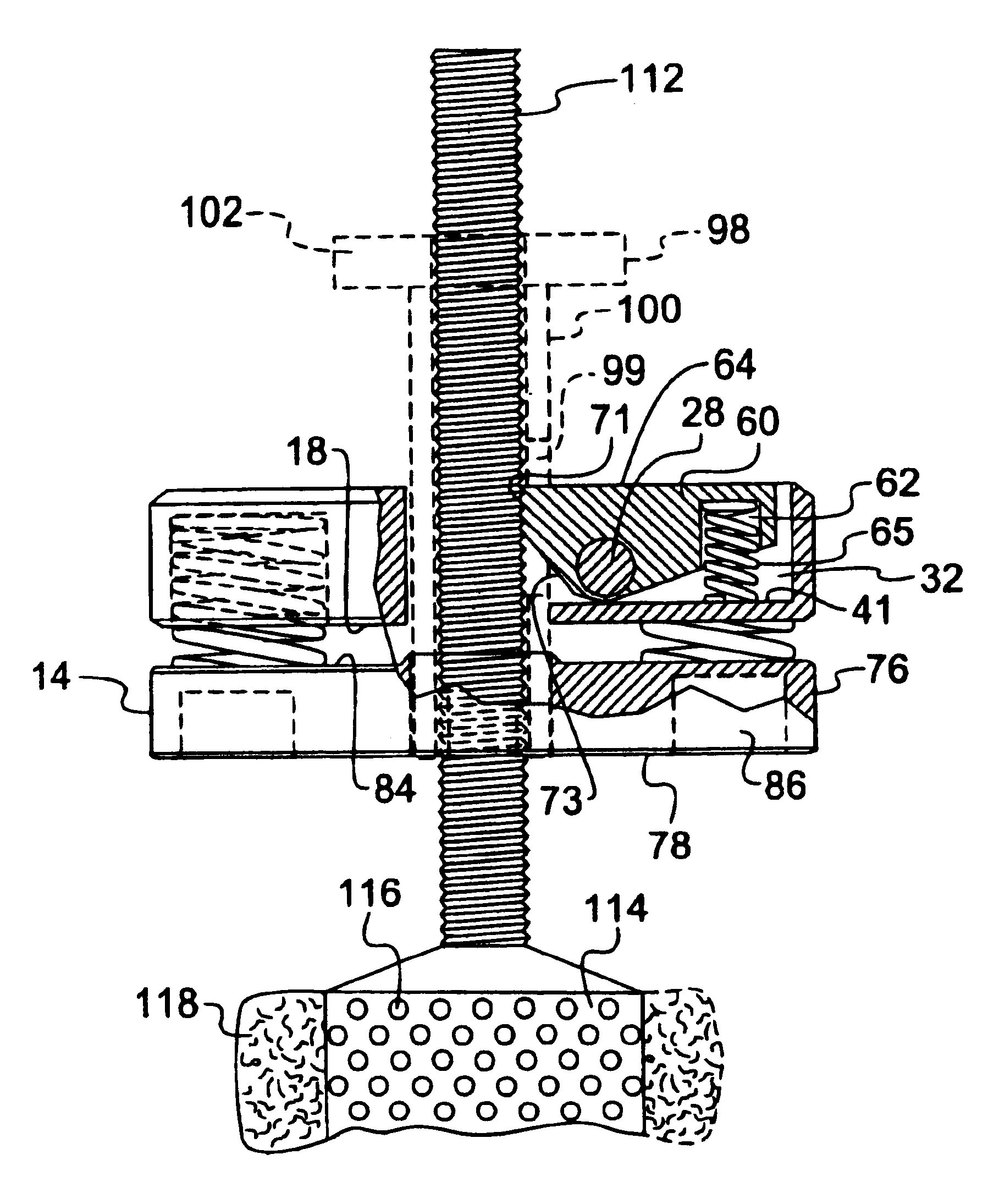
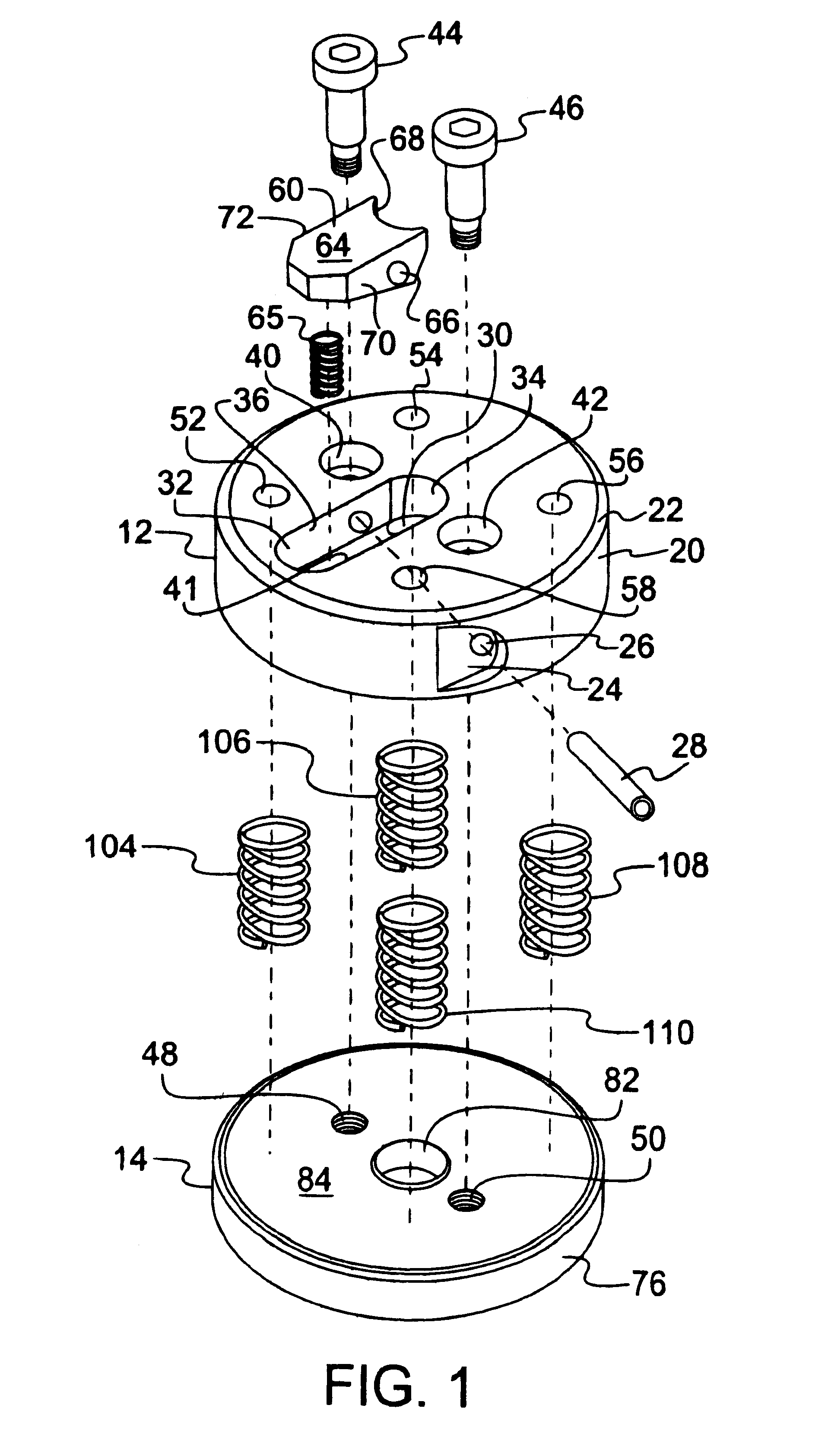
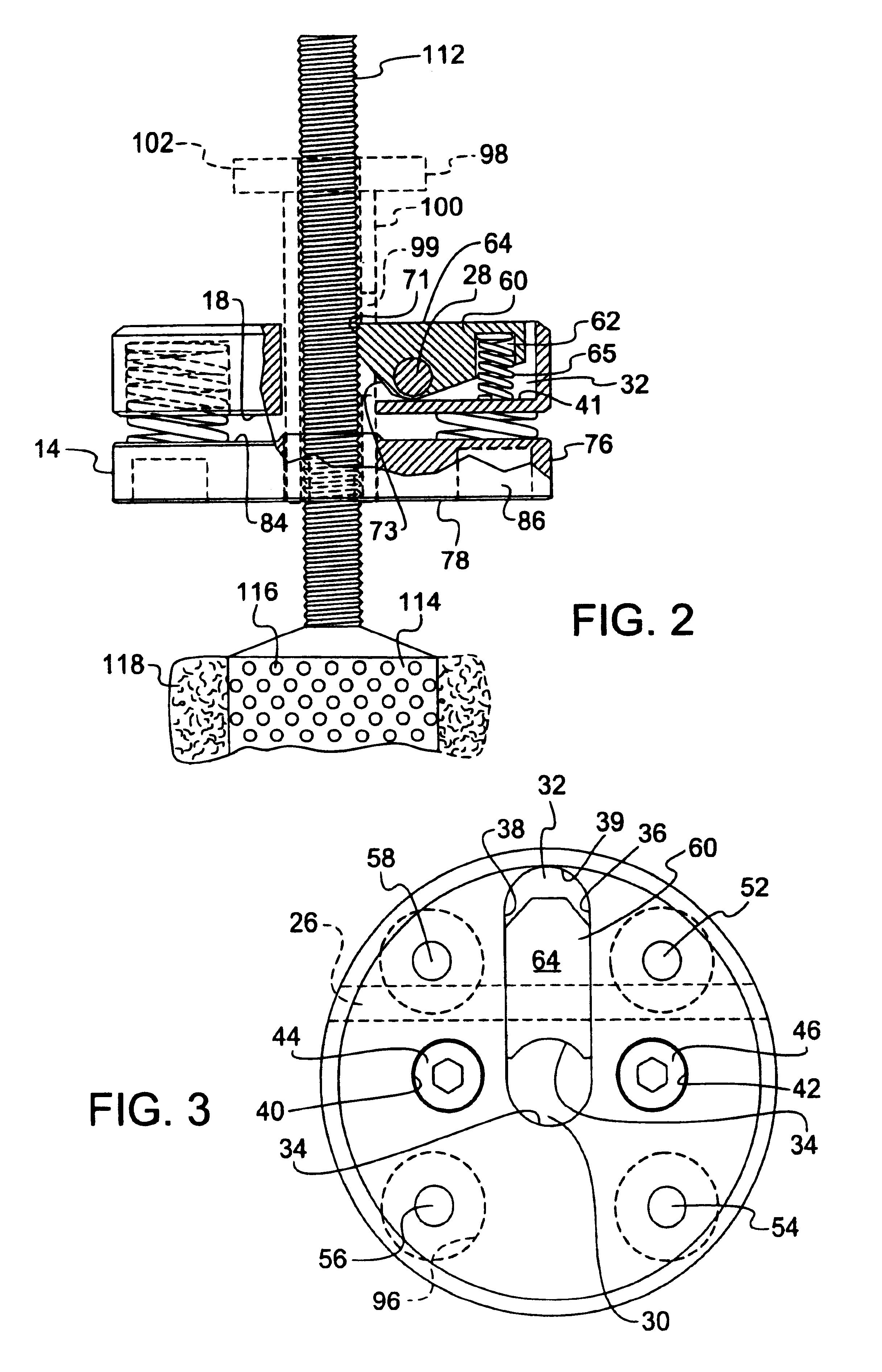
Referring now to the drawings, FIGS. 1-3 depict a locking assembly 10 according to one embodiment of the invention, as shown in exploded perspective view in FIG. 1, in front elevation, partial cross-section view in FIG. 2, as disposed on a threaded rod of a dye spindle on which is mounted a yarn roll, and in top plan view in FIG. 3.

The locking assembly 10 includes a main upper body member 12 joined to a main lower body member 14. The main upper body member 12 as shown is of a cylindrical block form with a main circular top surface 16, a main circular bottom surface 18 and a cylindrical side wall 20 which at its upper extremity may be beveled as illustrated. The side wall 20 may have a recess 24 therein, with an open end of the throughbore opening 26 in the recess accommodating insertion of the axle element 28 into the throughbore opening.

The main upper body member 12 has a central opening 30 therein for passage therethrough of a yarn roll spindle rod 112, as shown in FIG. 2. The cen...


PUM


Abstract

A yarn roll spindle locking assembly including a pivotally translating engagement/release mechanism. The locking assembly may be dropped onto a spindle to self-actuatingly lock in position and is readily removable from the spindle by manual depression of a release element. The locking assembly includes upper and lower body members coupled to one another so that the upper main body member and lower main body member are resiliantly biased apart from one another to provide the locking assembly with compression/expansion capability.

Description

1. Field of the InventionThis invention relates generally to a mechanical lock assembly of simple and manually operable character.2. Description of the Related ArtNumerous applications exist for mechanical locks having a quick-connect, quick-release character. In such applications, it is highly desirable, from the standpoint of ease of fabrication and use, to minimize the number of moving parts. Such minimization permits the lock assembly to be simply and efficiently manufactured, as well as rendering it highly reliable, since a minimum number of moving parts decreases wear and increases service life of the lock assembly since failure modes for the device are correspondingly reduced, in relation to more complex locks and structurally intricate locks having a large number of moving parts.In the textile industry, locking assemblies are employed to secure yarn rolls (typically called "packages" in the industry) on perforate spindles through which dye under high pressure is flowed into ...

Claims


Application Information

Patent Timeline
IPC IPC(8): D06B5/00D06B5/16
CPCD06B5/16
Inventor RATHBUN, RODERICK E.
Owner R TEX
Why Eureka
Try Eureka