Accelerometer sensor for detecting knocks and method for making same

a sensor and accelerator technology, applied in piezoelectric/electrostrictive devices, piezoelectric/electrostrictive device details, generators/motors, etc., can solve the problems of short circuits, metallic swarf generation, etc., and achieve the effect of repeating in mass production

Inactive Publication Date: 2001-04-10
SIEMENS AUTOMOTIVE
View PDF6 Cites 21 Cited by
  • Summary
  • Abstract
  • Description
  • Claims
  • Application Information

AI Technical Summary

Benefits of technology

is to produce an accelerometer-type sensor, in particular a pinging sensor, which is protected against the short-circuiting defects mentioned earlier, and which has accurate setting of the preload applied to the piezoelectric washer, this setting being assured of being very repeatable in mass-production.
Another object of the present invention is to produce a sensor of this kind which is inexpensive to manufacture.
As will be seen later on, the formation of this bulge generates no metallic swarf likely to produce a short-circuit in the sensor. Furthermore, the position of this bulge can be determined precisely, and this allows the preload on the piezoelectric washer to be set precisely.

Problems solved by technology

On the one hand, punching of this kind may generate metallic swarf and therefore the short-circuits mentioned earlier.

Method used


Image

  • Accelerometer sensor for detecting knocks and method for making same
  • Accelerometer sensor for detecting knocks and method for making same

Examples


Embodiment Construction

:

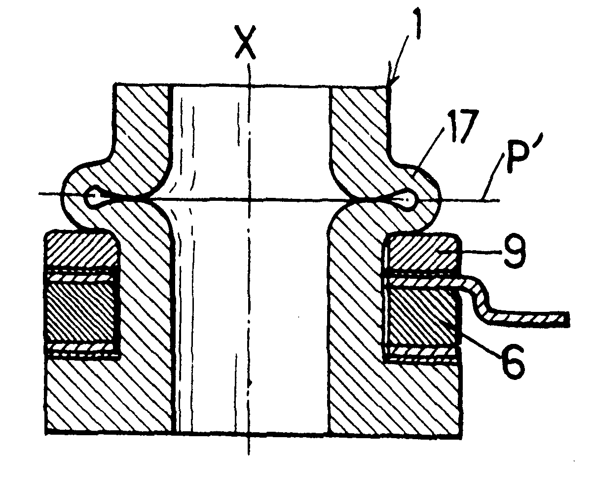
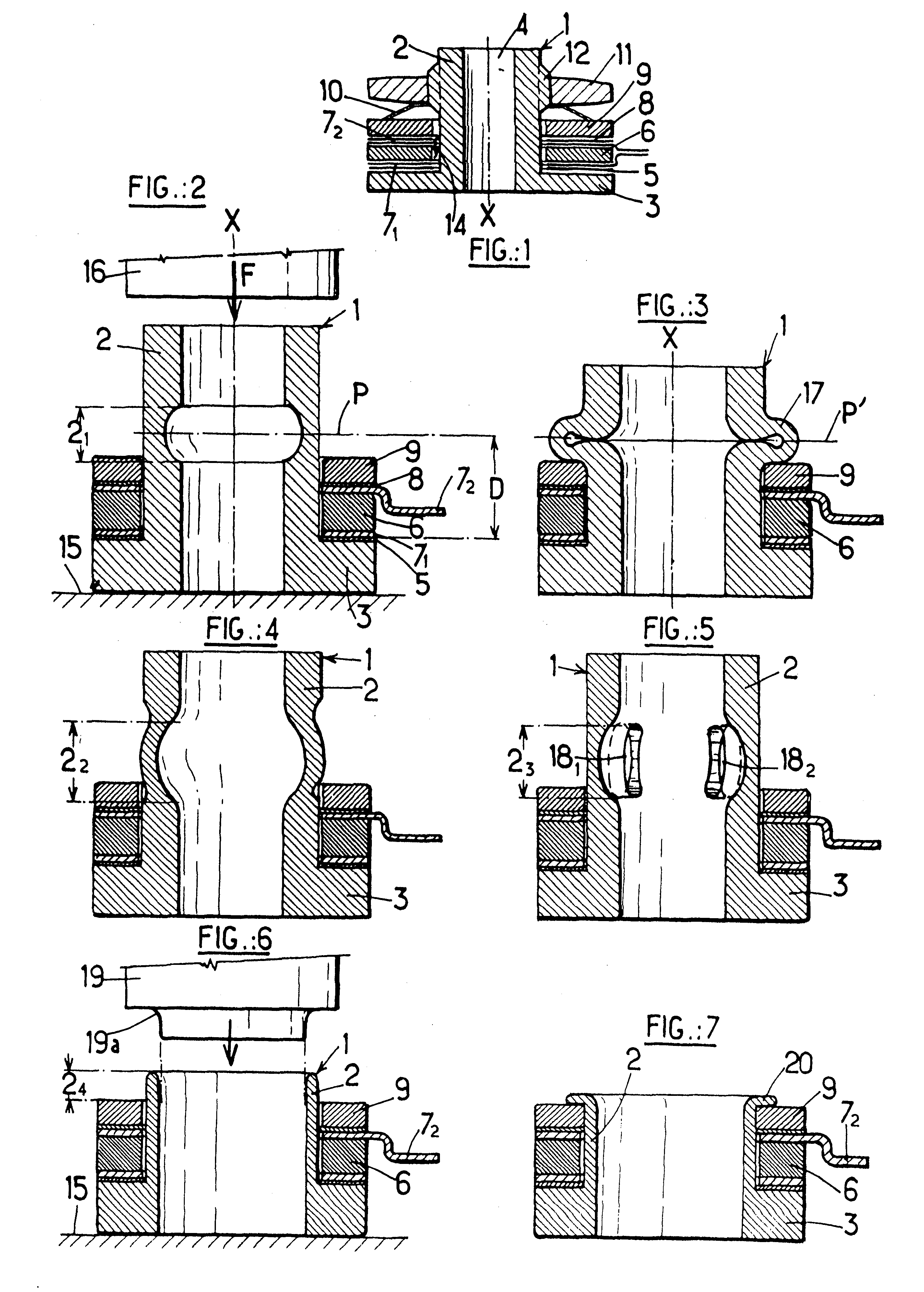
Reference is made to FIG. 2 of the appended drawing which depicts all of the parts of one embodiment of the sensor according to the invention, prior to the formation of the bulge constituting the retaining means mentioned earlier. In this FIG. and the subsequent FIGS., numerical references which are identical to those used in FIG. 1 depict components or elements which are identical or similar.

Thus, FIG. 2 again shows the base 1, its barrel 2 and its shoulder 3, the insulating washers 5 and 8, the piezoelectric washer 6 and its electrodes 7.sub.1, 7.sub.2 and the mass 9. Note the absence of the spring washer 10, although its presence is optional, as will be seen later.

FIG. 2 depicts the sensor according to the invention, in the stage of its manufacture which immediately precedes the formation of the returning means needed for assembling the various washers stacked up on the shoulder 3 of the barrel 1. The latter therefore has an exterior surface which is roughly cylindrical of revol...


PUM

PropertyMeasurementUnit
electrical voltageaaaaaaaaaa
axial forceaaaaaaaaaa
thicknessaaaaaaaaaa

Abstract

It comprises a) a cylindrical base (1) formed of an axial barrel (2) protruding from an annular shoulder (3), through both of which there passes an axial hole (4), b) a washer (6) made of a piezoelectric material slipped over the barrel, c) means (71, 72) for picking off the electrical voltage there is between two radial faces of said washer, e) an annular mass (9), also slipped over the barrel (2) and e) a retaining means collaborating with the annular shoulder (3) to trap said washer (6) and said mass (9) between them. The retaining means consists of a bulge (17) protruding radially from said barrel (2) and formed of the material of a predetermined portion thereof, deformed under an axial force for crushing said base (1).

Description

1. Field of the InventionThe present invention relates to an accelerometer-type sensor and, more specifically, to a sensor of this kind which is sensitive to the phenomena of pinging liable to affect the operation of an internal combustion engine.FIG. 1 of the appended drawing is a diagrammatic depiction, in an exploded view, of a known pinging sensor of the prior art, comprising a metallic cylindrical base 1 of axis X formed of an axial barrel 2 protruding from an annular shoulder 3, the barrel and the shoulder both having an axial hole 4 passing through them, the sensor further comprising a number of washers slipped over the barrel 2 and stacked on the shoulder 3. Thus, starting from this shoulder and stacked in this order, there are: a washer 5 made of an electrically insulating material, a washer 6 made of a piezoelectric material and its electrodes 7.sub.1, 7.sub.2, each one backing onto one of its axially-separated end faces, a second insulating washer 8, a weighty washer 9, a...

Claims


Application Information

Patent Timeline
Patent Type & Authority Patents(United States)
IPC IPC(8): G01L23/00G01L23/22G01P1/02G01P1/00G01P15/09G01M15/00
CPCG01L23/222G01P1/023G01P15/0907
Inventor CASTAING, JEAN-CHRISTOPHEBARRABES, PATRICK MICHELBRUYERE, JEAN-MARC
Owner SIEMENS AUTOMOTIVE
Why Eureka
Try Eureka