
Ceiling tile loudspeaker

a floor tile and loudspeaker technology, applied in the field of floor tiles, can solve the problems of poorer intelligibility off axis, and achieve the effect of supporting and propagating input vibrational energy

Inactive Publication Date: 2001-04-10
NEW TRANSDUCERS LTD
View PDF20 Cites 70 Cited by
  • Summary
  • Abstract
  • Description
  • Claims
  • Application Information

AI Technical Summary

Benefits of technology

Embodiments of the present invention use members of nature, structure and configuration achievable generally and/or specifically by implementing teachings of our patent application Ser. No. 08/707,012. Such members thus have capability to sustain and propagate input vibrational energy by bending waves in operative area(s) extending transversely of thickness often but not necessarily to edges of the member(s); are configured with or without anisotropy of bending stiffness to have resonant mode vibration components distributed over said area(s) beneficially for acoustic coupling with ambient air; and have predetermined preferential locations or sites within said area for transducer means, particularly operational

Problems solved by technology

While commonly used due to moderate cost and ready availability, these suffer from serious hot spot (excessive sound intensity) and directional effects and consequently poorer intelligibility off axis.

Method used


Image

  • Ceiling tile loudspeaker
  • Ceiling tile loudspeaker
  • Ceiling tile loudspeaker

Examples


Embodiment Construction

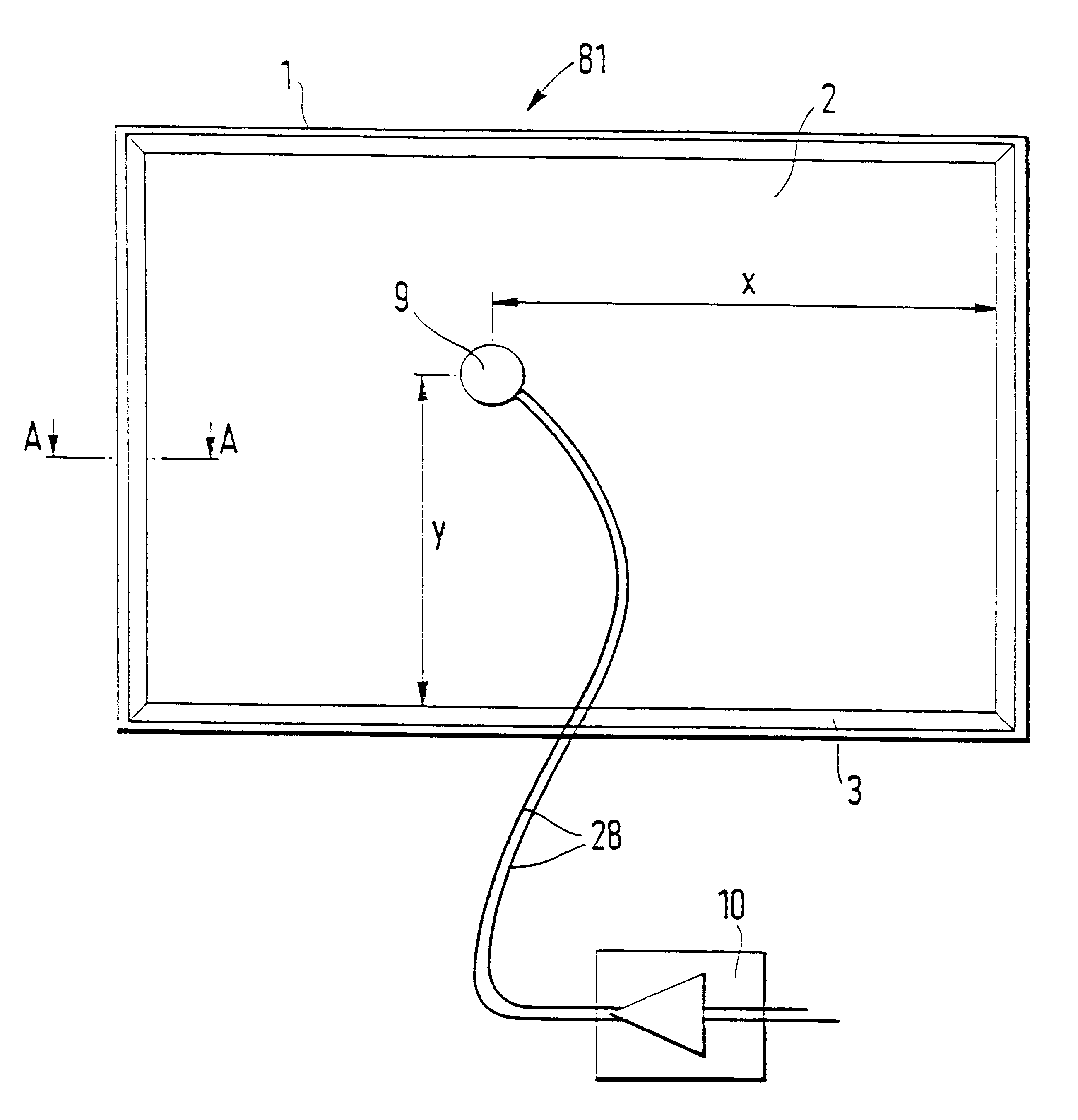
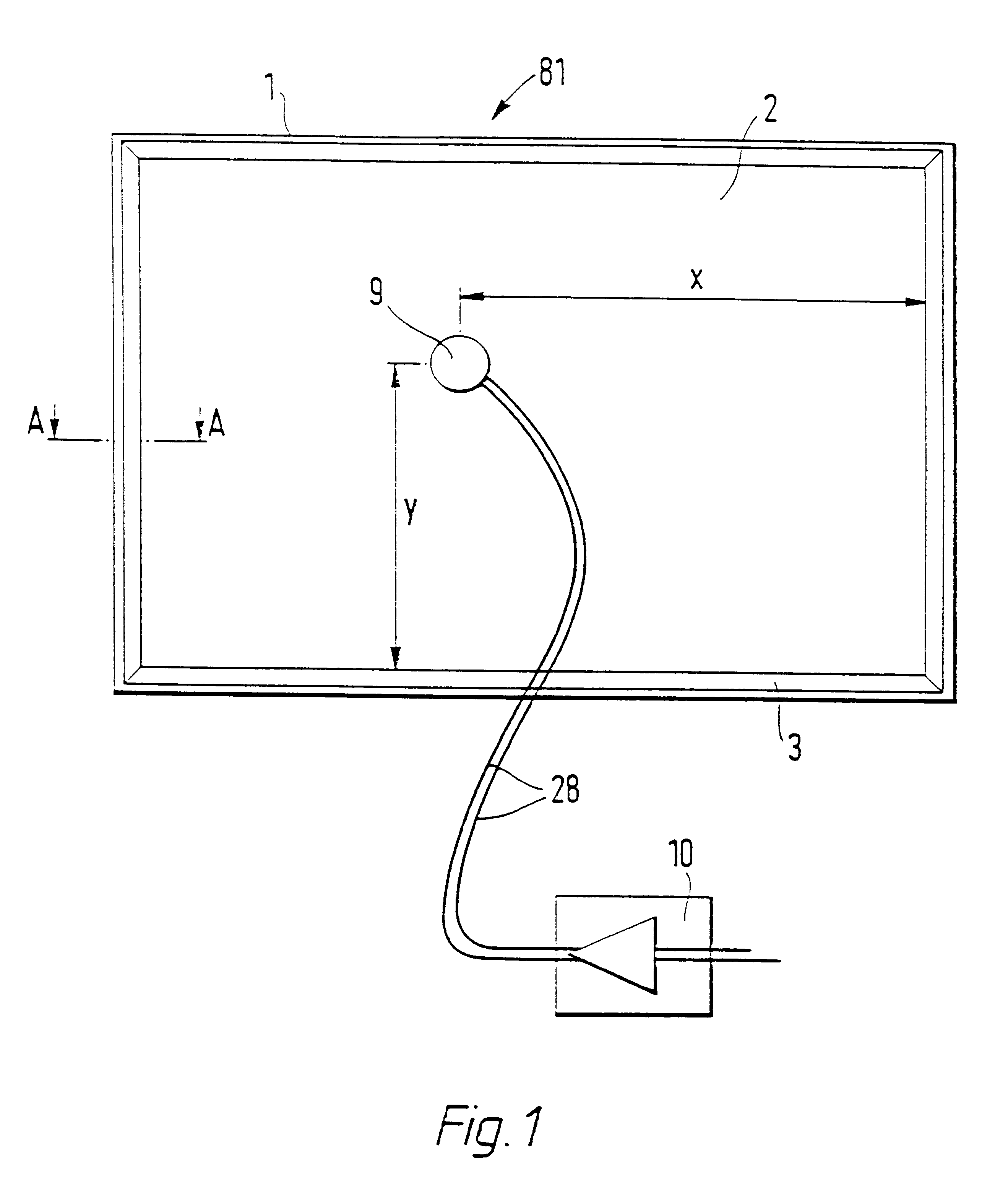
Referring to FIG. 1 of the drawings, there is shown a panel-form loudspeaker (81) of the kind described and claimed in our co-pending International application No. (our case P.5711) of even date herewith comprising a rectangular frame (1) carrying a resilient suspension (3) round its inner periphery which supports a distributed mode sound radiating panel (2). A transducer (9) e.g as described in detail with reference to our parent application No. 08 / 707,012 of even date herewith, is mounted wholly and exclusively on or in the panel (2) at a predetermined location defined by dimensions x and y, the position of which location is calculated as described in our co-pending International application No. (our case P.5711) of even date herewith, to launch bending waves into the panel to cause the panel to resonate to radiate an acoustic output.

The transducer (9) is driven by a signal amplifier (10), e.g. an audio amplifier, connected to the transducer by conductors (28). Amplifier loading a...


PUM


Abstract

A ceiling tile adapted to be supported in an overhead opening and function as a loudspeaker. The tile is in the form of a distributed mode acoustic radiator with a transducer mounted wholly and exclusively on the radiator at a location for coupling to resonant bending wave modes so as to vibrate the radiator and cause it to resonate.

Description

DESCRIPTION1. Technical FieldThe invention relates to loudspeakers and more particularly to loudspeakers comprising panel-form acoustic radiating elements.2. Background ArtIt is known from GB-A-2262861 to suggest a panel-form loudspeaker comprising:resonant multi-mode radiator element being a unitary sandwich panel formed of two skins of material with a spacing core of transverse cellular construction, wherein the panel is such as to have ratio of bending stiffness (B), in all orientations, to the cube power of panel mass per unit surface area (.mu.) of at least 10;a mounting means which supports the panel or attaches to it a supporting body, in a free undamped manner;and an electro-mechanical drive means coupled to the panel which serves to excite a multi-modal resonance in the radiator panel in response to an electrical input within a working frequency band for the loudspeaker.There is a wide application for sound distribution using speakers in standard module form, interchangeabl...

Claims


Application Information

Patent Timeline
IPC IPC(8): B42D15/02B60R11/02G06F1/16G06F9/02G07F9/02H04R5/00H04R3/04H04R9/02H04R7/08H04R7/06H04R9/04H04R5/02H04R1/28H04R17/00H04R1/26H04R1/24H04R7/00H04R9/00H04R5/027H04R1/22H04R1/02H04R9/06H04R7/04
CPCB42D15/022B60R11/0217G06F1/1605G06F1/1616G06F1/1688G06F9/02G07F9/02H04R1/021H04R1/025H04R1/028H04R1/24H04R1/26H04R1/2811H04R3/04H04R5/02H04R5/027H04R7/045H04R7/06H04R7/08H04R9/025H04R9/045H04R9/066H04R17/00H04R2201/021H04R2307/029H04R2440/07H04R2499/13H04R2499/15E04B9/04E04B9/0428E04B9/0442
Inventor AZIMA, HENRYCOLLOMS, MARTINHARRIS, NEIL JOHN
Owner NEW TRANSDUCERS LTD
Learn More