Flexible metal supporting device for a centrifugal separator

Inactive Publication Date: 2001-05-01
ALFA LAVAL AB
View PDF42 Cites 59 Cited by
  • Summary
  • Abstract
  • Description
  • Claims
  • Application Information

AI Technical Summary

Problems solved by technology

These known bearing supports comprise many details making them complicated and expensive.
The dampening properties of the friction buffers and of the rubber elements are difficult to calculate.
On the friction surfaces being dampened through friction, coatings (coke) are formed, which change the dampening properties and result in a great risk of jamming.
The dampening properties of the rubber material are difficult to predict and change over the time.
In the friction buffers, wear particles are formed, which reduce the working life of the bearing support.
The heat transfer is poor in these known bearing supports, since rubber has a low heat conducting capability and the friction surfaces of the friction buffers d

Method used


Image

  • Flexible metal supporting device for a centrifugal separator
  • Flexible metal supporting device for a centrifugal separator
  • Flexible metal supporting device for a centrifugal separator

Examples


Embodiment Construction

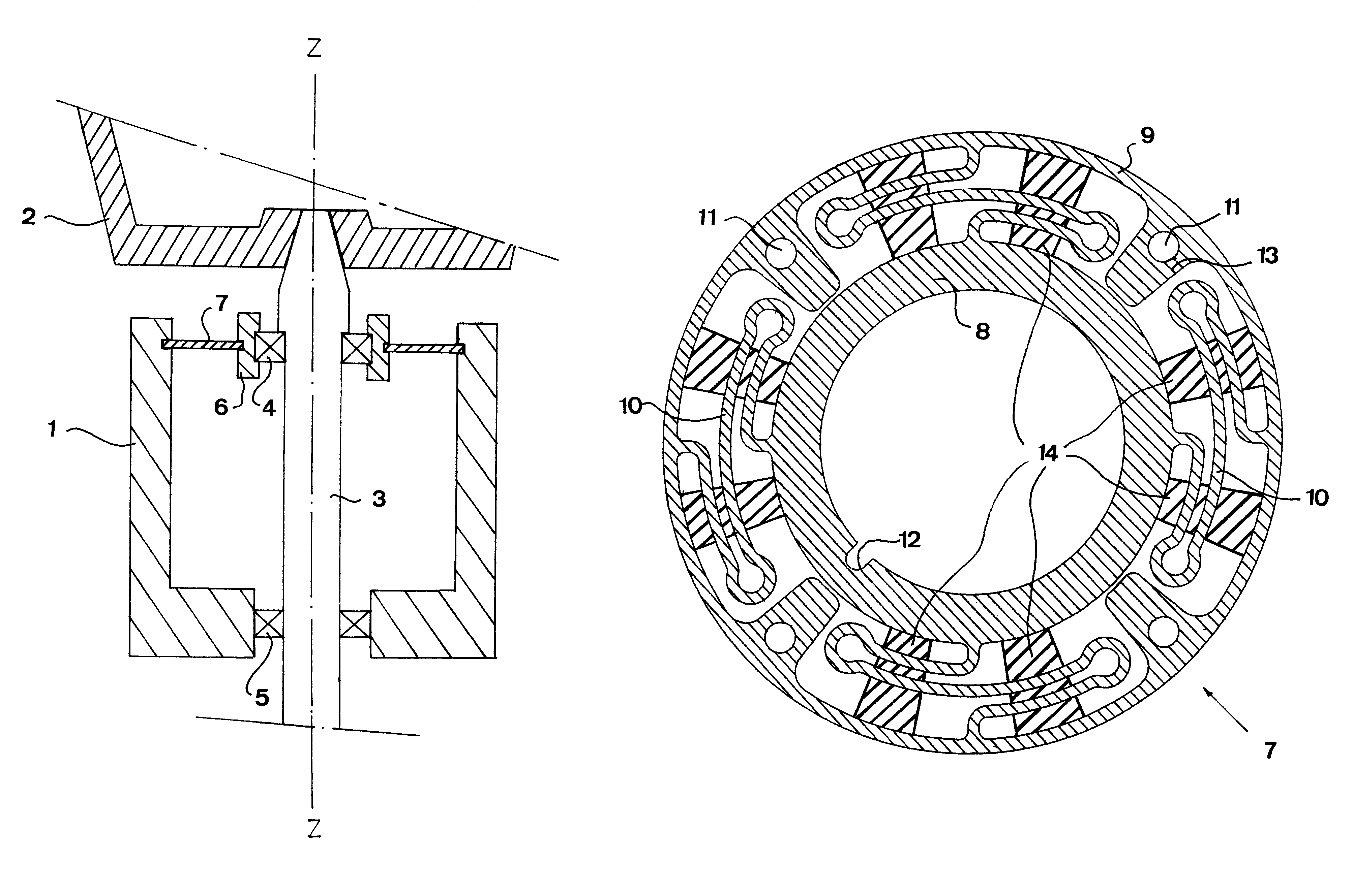
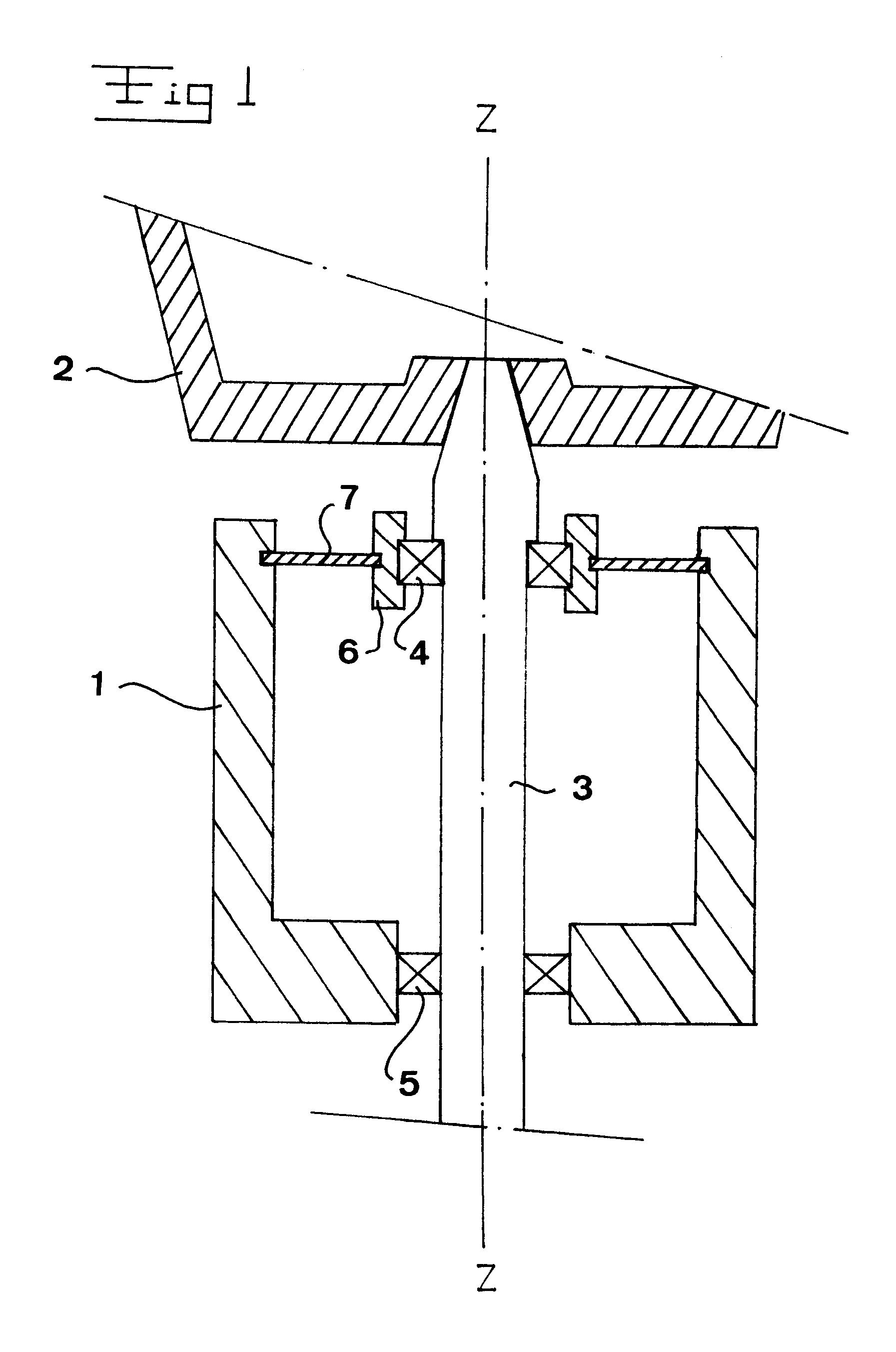
FIG. 1 discloses schematically a part of a centrifugal separator comprising a frame member 1 and a centrifuge rotor 2 which is fixedly connected to a rotor shaft 3. The centrifuge rotor 2 and the rotor shaft 3 are provided in the frame member 1 to be rotatable about a rotational axis z by means of an upper bearing 4 and a lower bearing 5. The lower bearing 5 is in direct contact with the rotor shaft 3 and the frame member 1, whereas the upper bearing 4 abuts the rotor shaft 3 by an inner bearing ring and abuts a bearing housing 6 by an outer bearing ring. The bearing housing 6 is connected to the frame member 1 by means of a support element 7 in accordance with the present invention. Thus, the upper bearing 4 is essentially immovable in relation to the rotor shaft 3 and in relation to the bearing housing 6. Consequently, movements of the rotor shaft 3 will be transferred to the support element 7 which is designed in such a manner that it permits small relative movements between the ...


PUM


Abstract

A flexible metal support device for a rotatable centrifuge rotor (2) provided in a frame member (1) by a bearing member (4). The support device comprises a support element (7) provided between the bearing member (4) and the frame member (1), and arranged to absorb relative movements between the centrifuge rotor and the frame member. The support element (7) comprises an inner mounting portion, essentially immovable in relation to the bearing member (4), and an outer mounting portion, essentially immovable in relation to the frame member (1). Moreover, the support element (7) comprises three flexible connecting portions which each extends between the inner and outer mounting portions and is arranged to absorb radial and axial relative movements between the centrifuge rotor and the frame member. Furthermore, the inner portion, the connecting portions and the outer portion form an integrated unit manufactured in one piece of metal material.

Description

THE BACKGROUND OF THE INVENTION AND PRIOR ARTThe present invention refers to a support device for a centrifugal separator having a centrifuge rotor, which is provided in a frame member to be rotatable about an axis of rotation by means of a bearing member, said support device comprising a support element provided between the bearing member and the frame member and arranged to absorb relative movements between the centrifuge rotor and the frame member, said support element comprising an inner mounting portion, which is arranged to be essentially immovable in relation to the bearing member, and an outer mounting portion, which is arranged to be essentially immovable in relation to the frame member.The present invention will be described in connection with a so called upper bearing support of a centrifugal separator. However, it is to be noted that the invention is applicable also to other bearing supports of centrifugal separators. Such conventional bearing supports are essentially of...

Claims


Application Information

Patent Timeline
IPC IPC(8): B04B9/00B04B9/12F16C35/04F16C27/04F16C35/077F16C27/00
CPCB04B9/12F16C27/04F16C35/077
Inventor BENGTSSON, LEIFGRANDIN, STAFFANHJELM, JONASKLINTENSTEDT, KJELLLARSEN, TORBJORNOHLSON, NILS-GUNNARSETTERBERG, JAN
Owner ALFA LAVAL AB
Why Eureka
Try Eureka