ATM cell multiplexer

a technology of atm cell and multiplexer, which is applied in the field of atm cell multiplexer, can solve the problems of complex control of software/hardware, high manufacturing cost,

Inactive Publication Date: 2001-05-01
FUJITSU LTD
View PDF6 Cites 16 Cited by
  • Summary
  • Abstract
  • Description
  • Claims
  • Application Information

AI Technical Summary

Problems solved by technology

However, the ATM switch is disadvantageous in that the manufacturing cost is highly expensive and the control of the software / hardware is complicated, requiring a large-sized unit.

Method used


Image

  • ATM cell multiplexer
  • ATM cell multiplexer
  • ATM cell multiplexer

Examples


Embodiment Construction

Hereinafter will be described embodiments of an ATM cell multiplexer according to the present invention.

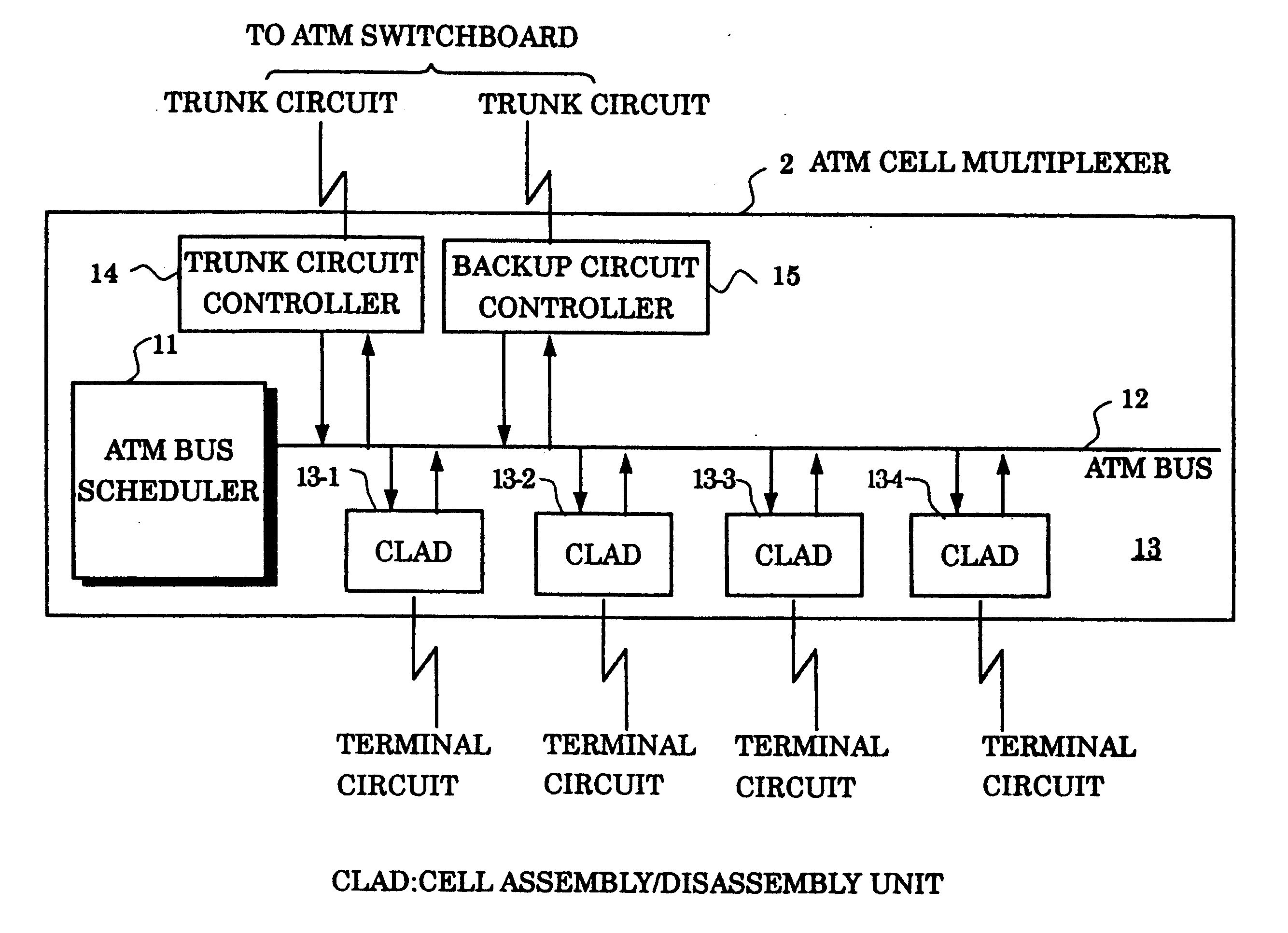
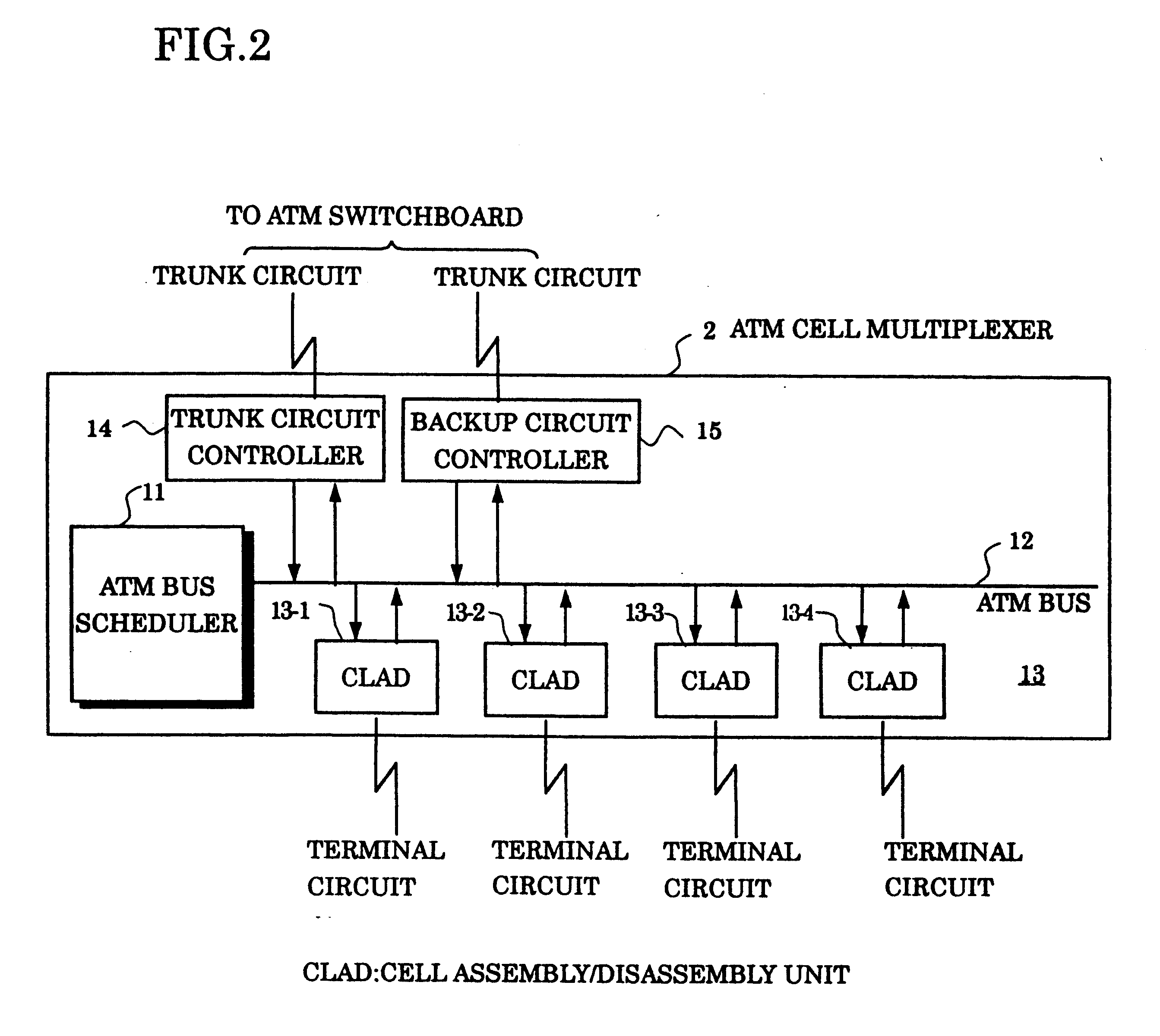
FIG. 3 shows a specific embodiment of the ATM cell multiplexer. This ATM cell multiplexer is composed of; a main card 11 having installed therein an ATM bus scheduler and a CPU for SVC controls; a backboard 12 having an ATM cell bus 121 and an inter-processor control bus 122; a trunk card 14 as a trunk circuit control unit connected between trunk circuits (basic trunk circuit) and the buses 121, 122; a backup card 15 as a backup circuit control unit connected between backup circuits and the buses 121, 122; a CLAD card 13 having installed therein a cell assembly / disassembly function; an LCD unit 18 as a display portion; and a power source 19. The CLAD card 13 includes voice trunk CLAD card 13-1 and V / X CLAD card 13-2 where the CPU is stored.

A general-purpose high speed digital interface is used for the above-mentioned trunk circuit and the backup circuit. For such an interface, an ...


PUM


Abstract

An ATM cell multiplexer is arranged so that in the up direction from the terminal equipments/ATM cell interfaces to the ATM switchboard the ATM bus scheduler allocates the transmission rights for each CLAD unit in accordance with a preset schedule table and predetermined service categories or traffic control for the transmission of cells, and in the down direction from the ATM switchboard to the terminal equipments/ATM cell interfaces the cells are broadcast to all of the CLAD units which decide for the reception of the cells as to whether or not the cells are addressed to themselves.

Description

1. Field of the InventionThe present invention relates to an ATM cell multiplexer, and in particular to an ATM cell multiplexer connected between terminal equipments and an ATM switchboard. "ATM (Asynchronous Transfer Mode)" technology is expected as a communication technology for realizing a multi-media society, and has been developed for fast data used in an inter-computer communication etc.However, as seen from a recent ATM forum, a network is demanded in the market where the communication protocols of the prior art such as for voices, HDLC (High level Data Link) and FR (frame relay) can also be interworked with the ATM technology.When such a network is constructed, it is useful to set up an ATM cell multiplexer as an apparatus in branch circuit or line system in order to construct an ATM switchboard (ATM switch) as a key network and to increase the accommodation efficiency of circuits with terminal equipments.2. Description of the Related ArtFIG. 1 shows a general arrangement of...

Claims


Application Information

Patent Timeline
Patent Type & Authority Patents(United States)
IPC IPC(8): H04Q11/04H04L12/56H04L47/43H04Q3/00H04L47/52H04L47/6275
CPCH04Q11/0478H04L2012/5652H04L2012/5672
Inventor SHIBATA, KENJIFURUKAWA, KAZUNORIONO, YOSHIHISA
Owner FUJITSU LTD
Why Eureka
Try Eureka