X-ray tube

a technology of x-ray tube and snout, which is applied in the field of x-ray tube, can solve the problems of high field emission, instability, and low focus of x-ray tubes with flat gun container snouts

Inactive Publication Date: 2001-05-08
KEVEX X RAY
View PDF1 Cites 72 Cited by
  • Summary
  • Abstract
  • Description
  • Claims
  • Application Information

AI Technical Summary

Problems solved by technology

However, investigations conducted by the present inventors have shown that a flat gun snout tends to produce high field emission and instability when positioned nearer a target due to high electric fields.
Consequently, such x-ray tubes with flat gun container snouts are focus limited due to chromatic aberration and instability issues, especially if attempts are made to position the gun assembly in closer proximity to the target.

Method used


Image

  • X-ray tube
  • X-ray tube
  • X-ray tube

Examples


Embodiment Construction

Illustrative embodiments and exemplary applications will now be described with reference to the accompanying drawings to disclose the advantageous teachings of the present invention.

While the present invention is described herein with reference to illustrative embodiments for particular applications, it should be understood that the invention is not limited thereto. Those having ordinary skill in the art and access to the teachings provided herein will recognize additional modifications, applications, and embodiments within the scope thereof and additional fields in which the present invention would be of significant utility.

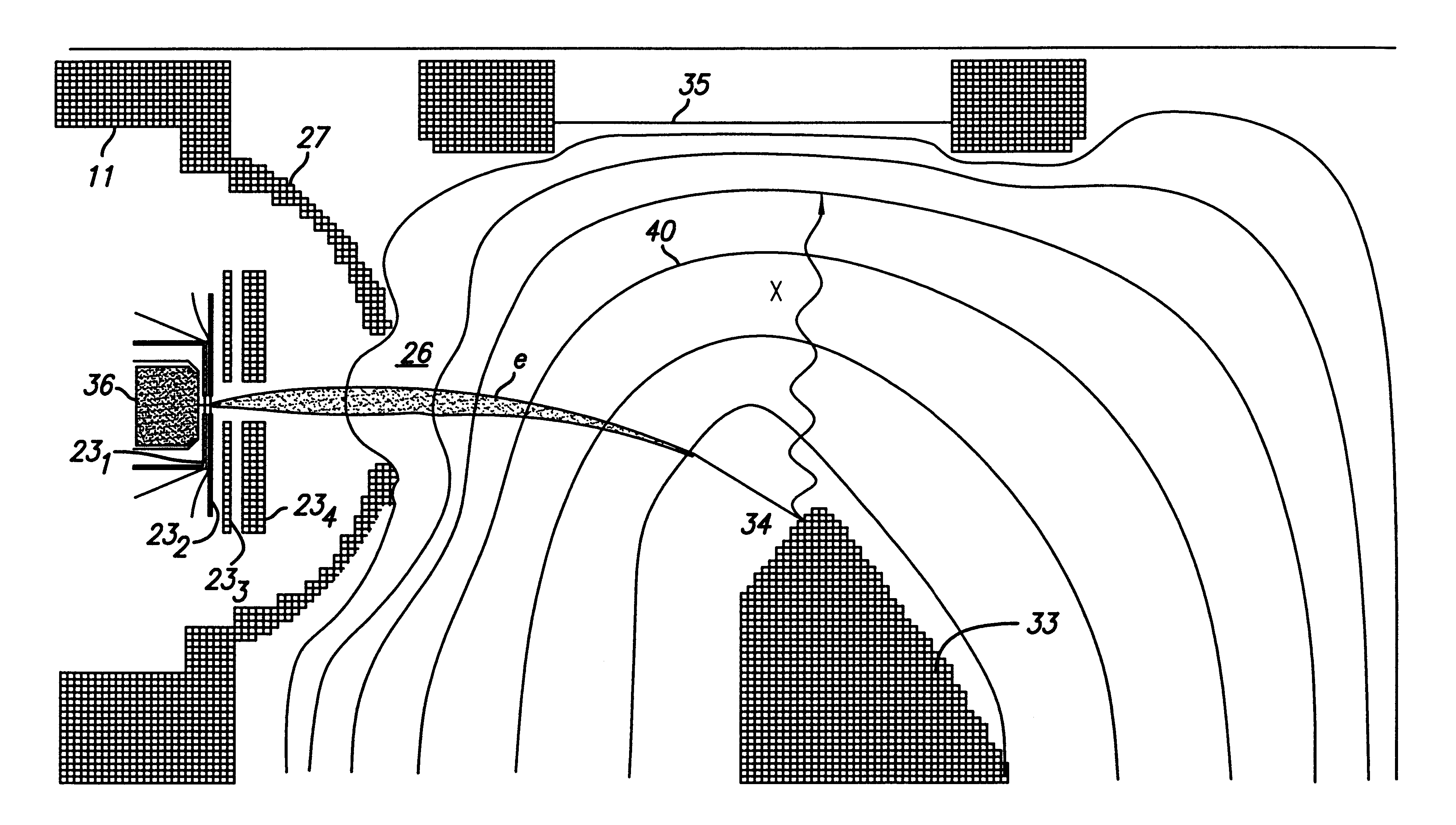
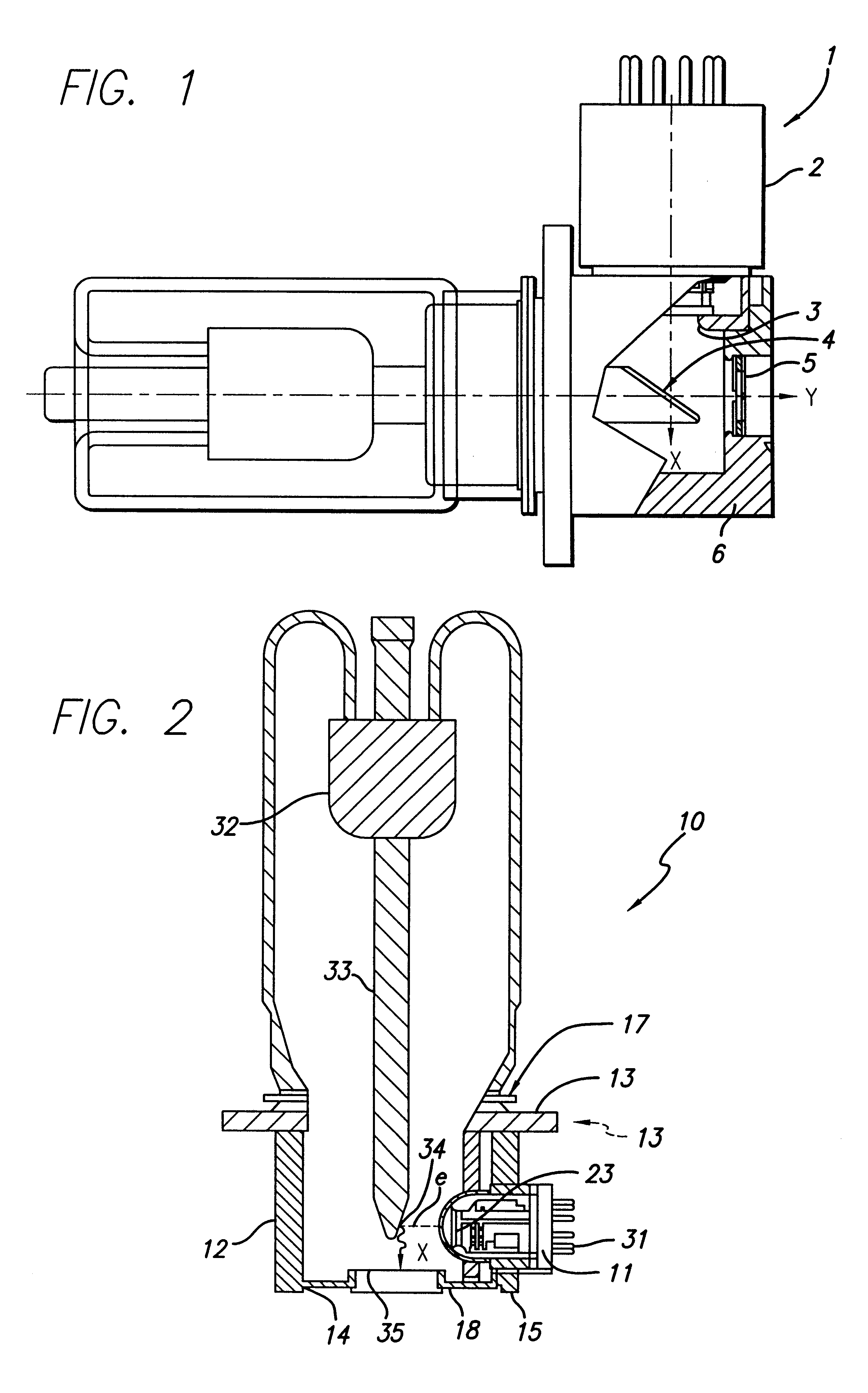
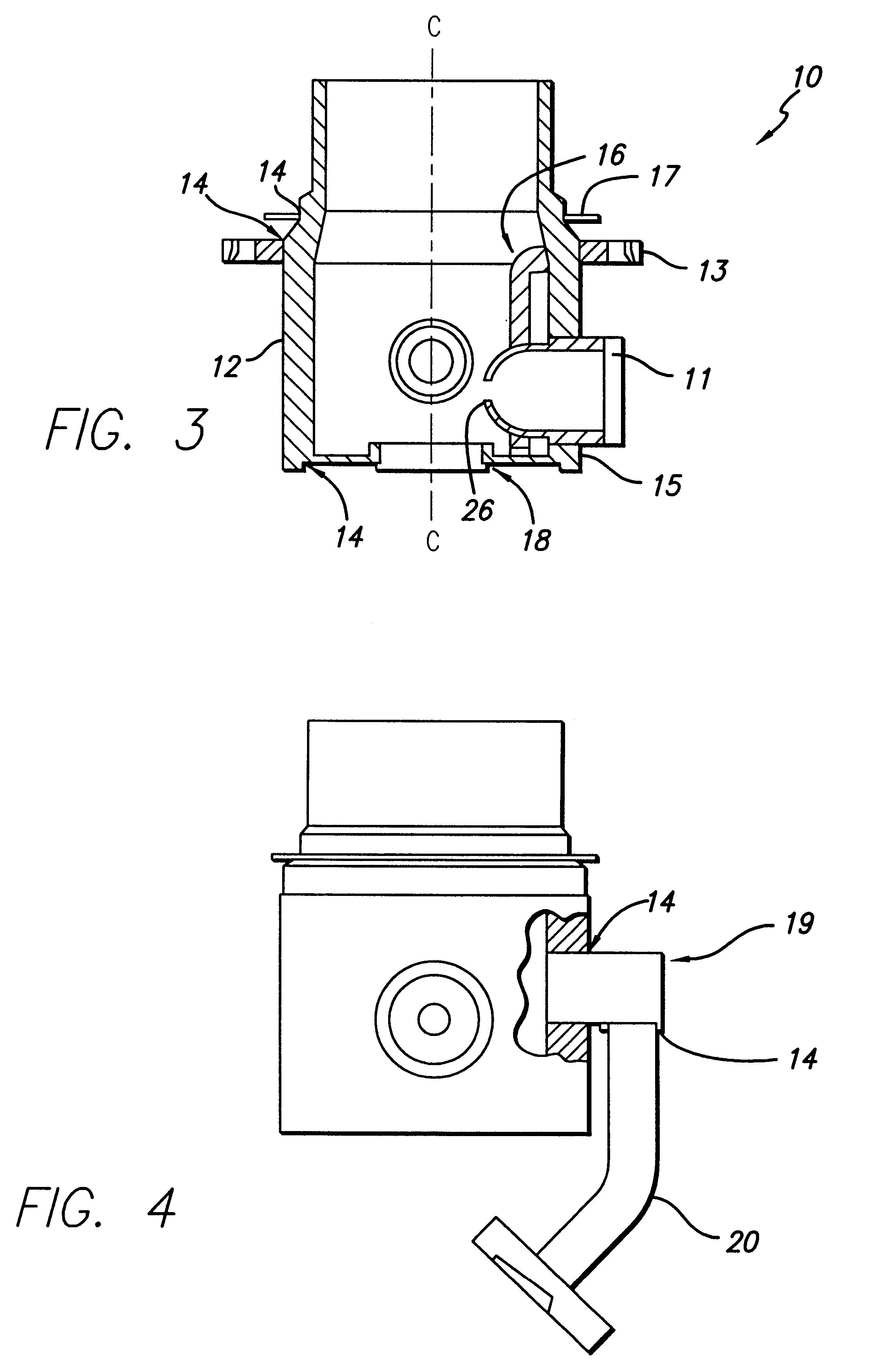
FIG. 2 illustrates an x-ray tube generally indicated by 10 comprising an anode 34 and a means for generating a beam of electrons. The electron gun assembly 11 and the anode 34 are both disposed inside an air evacuated housing or envelope body 12 including an x-ray transparent window 35. The electron gun assembly 11 is provided with electrical connectors 31 for t...


PUM


Abstract

An x-ray tube comprising an electron gun assembly having an electron gun container housing an electron generator for generating electrons in a first direction along a first axis. The beam of electrons impinges upon an anode which emits x-rays in response to the beam of electrons. The gun container is characterized by having a discharge end comprising a solid spherical shape.

Description

1. Field of the InventionThe present invention relates to an x-ray tube. More specifically, the present invention relates to an x-ray tube configuration capable of generating high intensity x-rays that emanate from a small focal spot without a loss of reliability.2. Description of the Related ArtX-ray tubes have a number of applications which involve the treatment or analysis of a sample, for example, industrial imaging, analytical instruments and medical imaging. For such applications, it is often desirable to have an x-ray tube which has a long service life, which is capable of forming a small focal spot and which is also capable of generating a high intensity of x-radiation at the sample.X-ray tubes generally include an electron gun and an anode. A beam of electrons generated by the electron gun is focused to a focal spot on the anode, and x-rays are generated by the interaction of the beam of electrons with the atoms of the anode. These x-rays are generated in all directions emi...

Claims


Application Information

Patent Timeline
Patent Type & Authority Patents(United States)
IPC IPC(8): H01J3/02H01J3/00H01J35/14H01J35/00
CPCH01J3/027H01J35/14H01J2235/06H01J35/147
Inventor ENCK, RICHARD S.JOHNSON, RICHARD G.
Owner KEVEX X RAY
Why Eureka
Try Eureka