Grounding clip for computer peripheral cards

a technology for peripheral cards and grounding clips, which is applied in the direction of electrical apparatus casings/cabinets/drawers, coupling device connections, casings/cabinets/drawers details, etc., and can solve problems such as additional parts, failure of host devices, and build-up of electrical charges on the pcb

Inactive Publication Date: 2001-05-15
CISCO TECH INC
View PDF4 Cites 24 Cited by
  • Summary
  • Abstract
  • Description
  • Claims
  • Application Information

AI Technical Summary

Benefits of technology

The present invention advantageously provides the ability to discharge a peripheral card prior to connection with the host device. This is accomplished by using the discharge surface of the fingers to direct any charge that has been built up on the peripheral card to a low impedance, high frequency grounding point. Hence, damage to the circuitry of the host device, as a result of electrical discharge from the peripheral card, is eliminated.

Problems solved by technology

One of the major problems encountered in manufacturing and handling peripheral cards is the build-up of electrical charges on the PCB.
Since the edge connectors are in direct electrical communication with various components in the host device, the discharge of electrical energy from the peripheral card can cause significant damage to the circuit, which can, on occasions, lead to failure of the host device.
Such an arrangement, however, requires additional parts and increases manufacturing costs in order to properly route the requisite number of traces to the grounding edge of the peripheral card.
Accordingly, one disadvantage associated with current peripheral cards is the inadvertent build-up of electrical charges that can potentially destroy circuitry on the host device that will receive the peripheral card.
Another disadvantage associated with current peripheral cards is the extended manufacturing steps traditionally required to properly provide a grounding point.

Method used


Image

  • Grounding clip for computer peripheral cards
  • Grounding clip for computer peripheral cards
  • Grounding clip for computer peripheral cards

Examples


Embodiment Construction

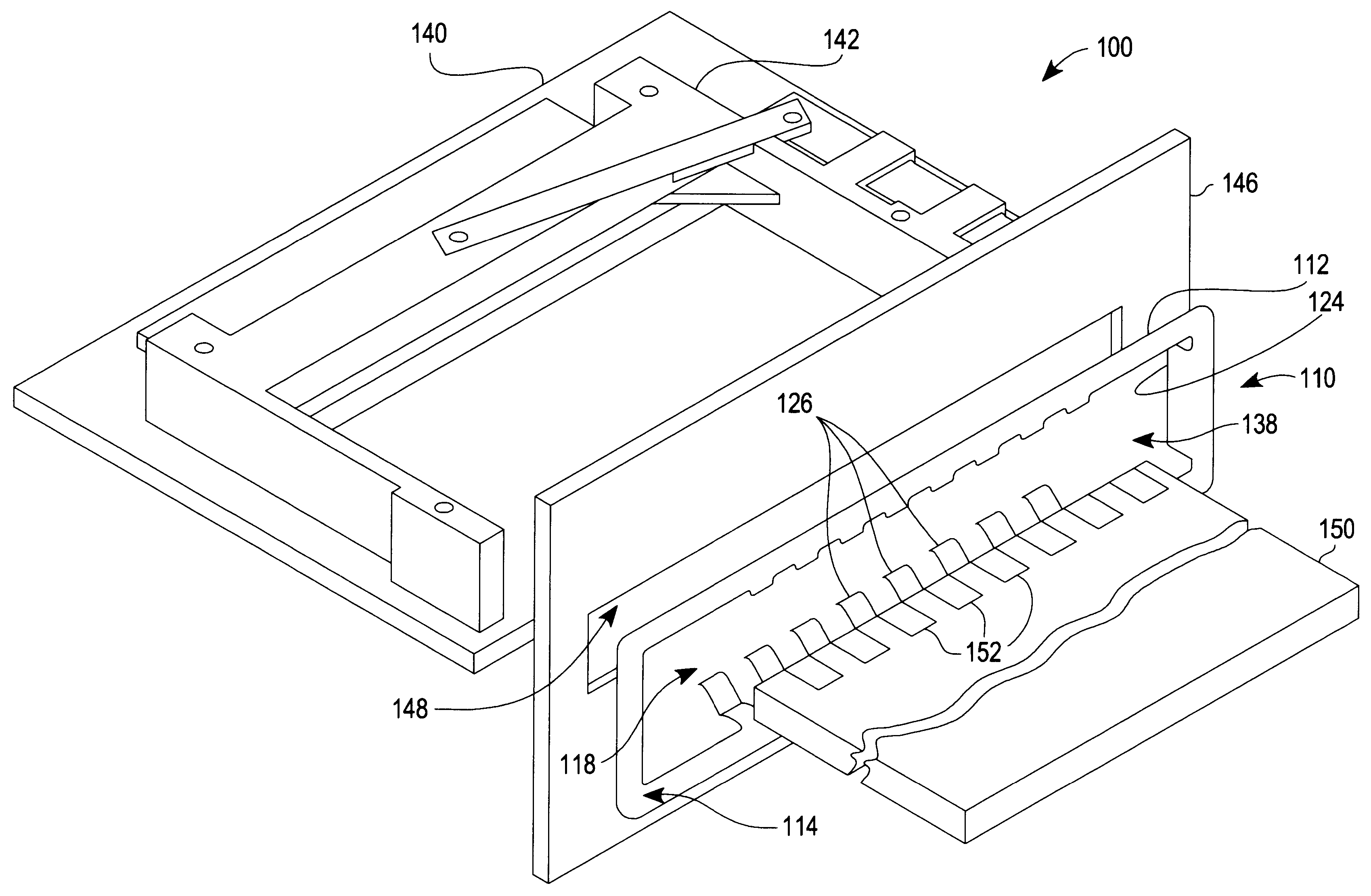
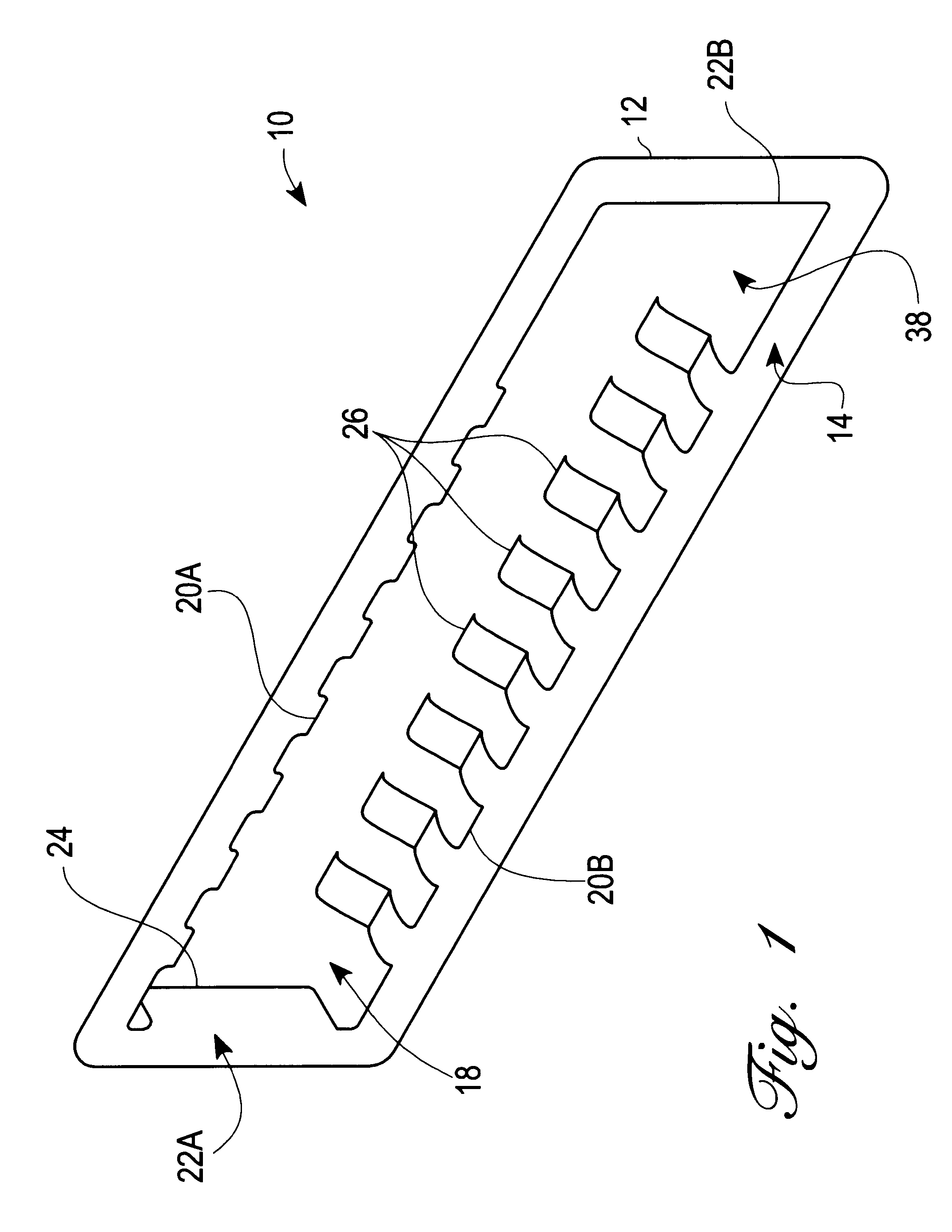
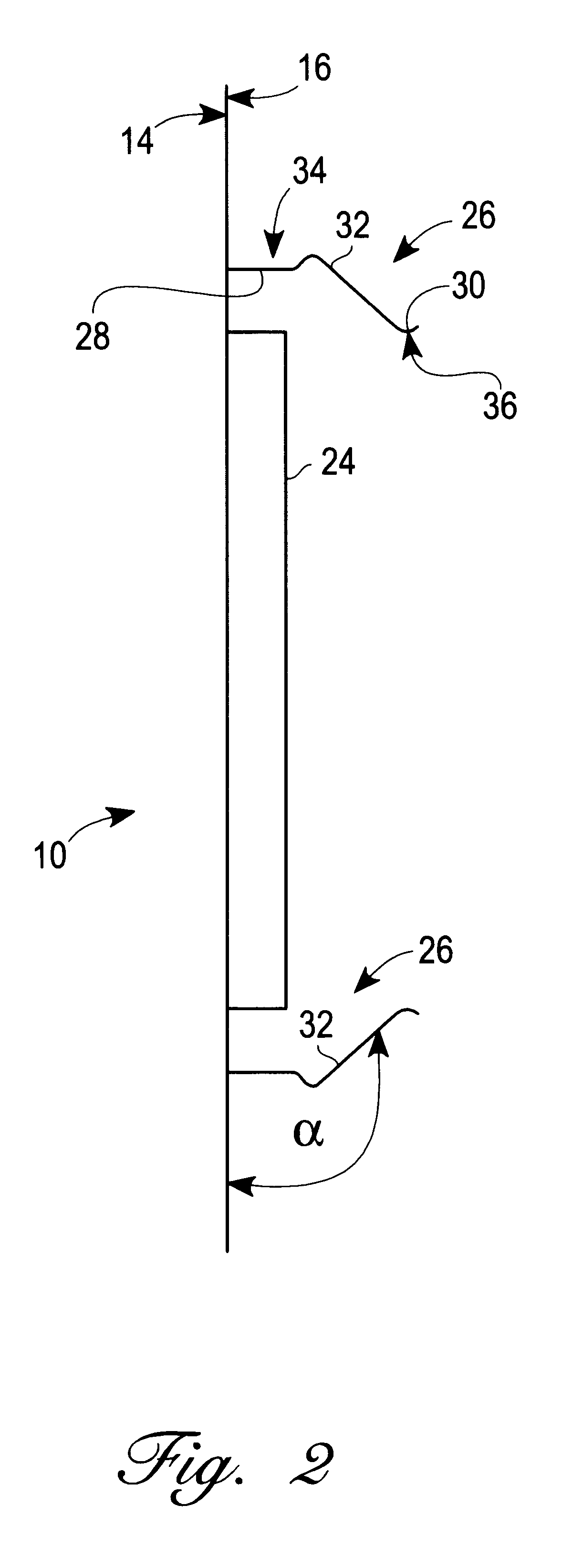
An embodiment of the present invention is schematically illustrated in FIGS. 1-4, wherein similar features and parts bear similar reference numerals. Referring initially to FIG. 1, a grounding clip 10 for a peripheral card is shown. The grounding clip 10 is in the form of a base 12 having a generally rectangular shape. The base 12 of the clip includes a rear surface 14 and, as best seen in FIG. 2, a contact surface 16. The grounding clip 10 contains an aperture 18 that is defined by internal length portions 20A, 20B (collectively 20) and internal width portions 22A, 22B (collectively 22) of the base 12.

As illustrated in FIG. 1, the aperture 18 also has a rectangular configuration. While not explicitly shown, the aperture 18 is appropriately sized to receive the specific peripheral card that will be discharged by the grounding clip. Such a card can, for example, be a PCMCIA card. A pair of alignment tabs 24 is formed along the internal width portions 22 of the grounding clip 10. As s...


PUM


Abstract

A grounding clip for computer peripheral cards includes a base and at least one finger. The base has a contact surface and contains an aperture. Further, the aperture is sized to receive the particular peripheral card that must be discharged by the grounding clip. The finger extends from an internal length portion of the base, and in the case where a plurality of fingers are provided, they paired and disposed in registry along opposing internal length portions of the base. Each finger includes a discharge surface for contacting and grounding the peripheral card.

Description

1. Technical FieldThe present invention relates to packaged electronic assemblies, and, more particularly, to a grounding clip for computer peripheral cards.2. Description of the Related ArtElectronic devices such as computers, laptops, personal digital assistance (PDA's), etc. utilize various types of interfaces in order to exchange data and expand their capabilities. For example, personal computers utilize parallel, serial, and bus interfaces to connect to external devices and exchange data. Bus interfaces often take the form of a slot connected to a printed circuit board that contains electrical contacts, and are sized to receive peripheral cards designed to meet specific standards. Examples of such standards include the Industry Standard Architecture (ISA), the Peripheral Component Interconnect (PCI), and the Personal Computer Memory Card International Association (PCMCIA).The PCMCIA standard has been extensively refined to provide the requirements for accommodating a variety of...

Claims


Application Information

Patent Timeline
Patent Type & Authority Patents(United States)
IPC IPC(8): H01R13/648H05K5/02H05K9/00
CPCH01R13/6485H05K5/0265H05K5/0286H05K9/0067Y10S439/939
Inventor STUTTS, JIMKOZAK, FREDERICKORZIK, JIMEASTMAN, SCOTT
Owner CISCO TECH INC
Why Eureka
Try Eureka