Acupuncture device with improved needle guide tube

Inactive Publication Date: 2001-05-15
GAVRONSKY STAS
View PDF7 Cites 19 Cited by
  • Summary
  • Abstract
  • Description
  • Claims
  • Application Information

AI Technical Summary

Benefits of technology

The acupuncture device of the present invention consists of an acupuncture needle and a guide tube having a longitudinal slot or notch at the upper end of the tube which is wider than the diameter of the needle handle. A practitioner can easily secure the upper portion of the handle in this notch by pressing on the handle of the needle with his/her index finger. In angular insertions, the practitioner can maintain the desirable diagonal position of the needle inside the guide tube. The acupuncture procedure is facilitated due to the fact that a larger portion of the needle handle projects from the guide tube through the notch. According to a

Problems solved by technology

On the other hand, the relatively big diameter of the tube compromises the precision of the insertion.
Hence, the angle at which the needle is inserted into the point is unpredictable.
Furthermore, when the practitioner attempts to insert a needle at sharp angles, such as on the face or head of the patient, the acupuncture needle tends to slide downward, out of the guide tube.
This makes the regular insertion technique very uncomfortable, if not impossible.
Also, the clearance C is too small for full penetration of the tip of the needl

Method used


Image

  • Acupuncture device with improved needle guide tube
  • Acupuncture device with improved needle guide tube
  • Acupuncture device with improved needle guide tube

Examples


Embodiment Construction

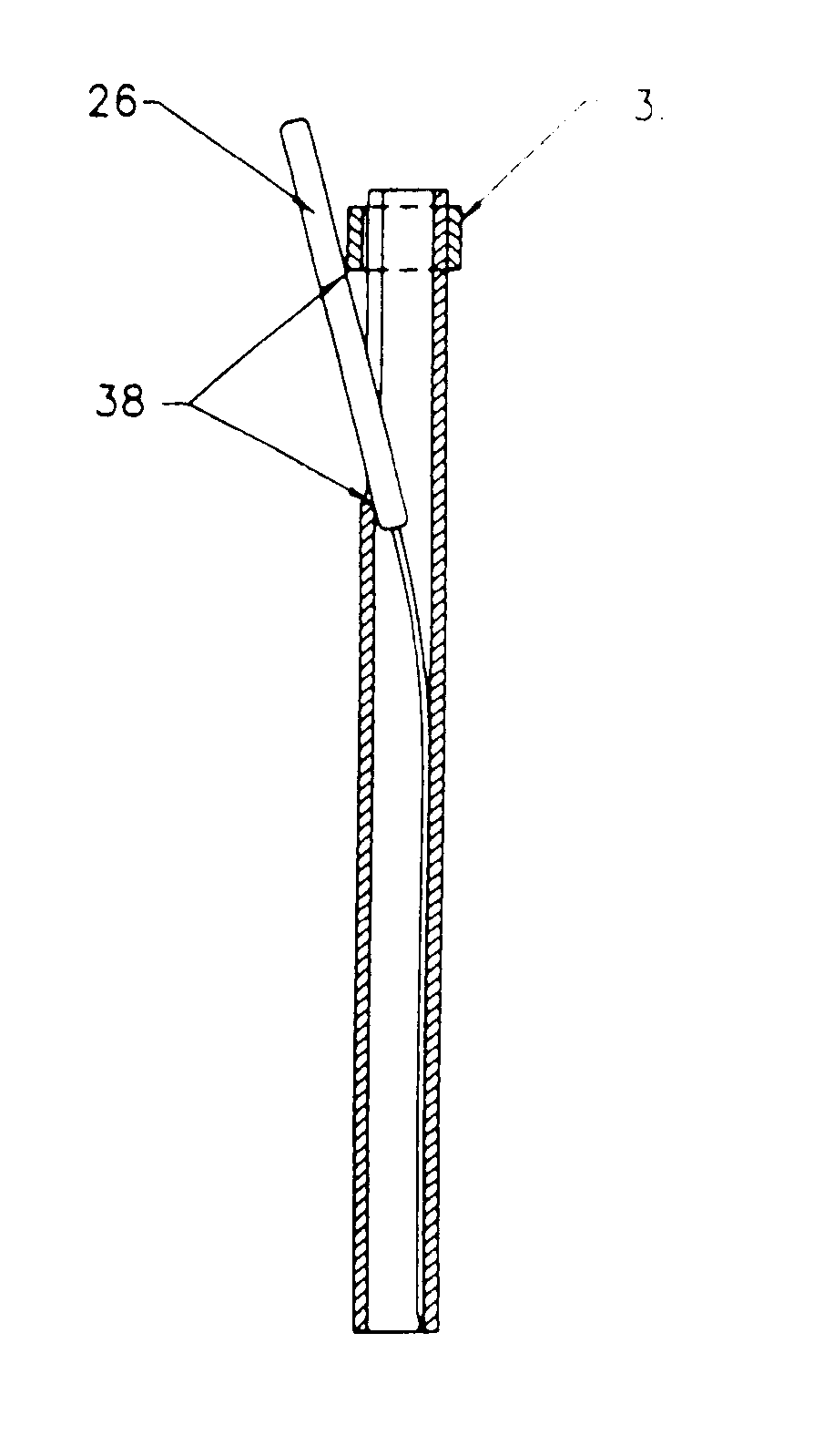
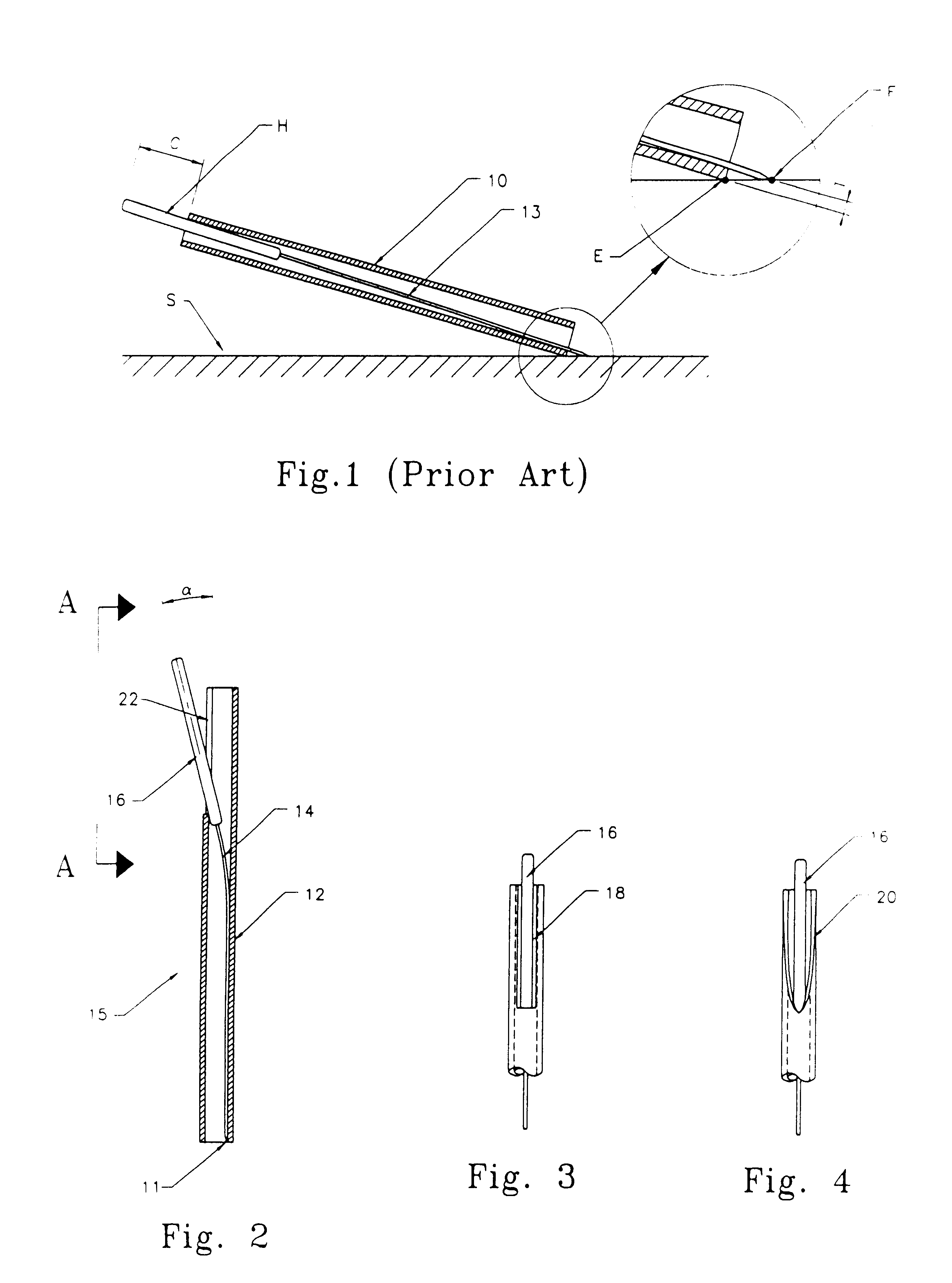
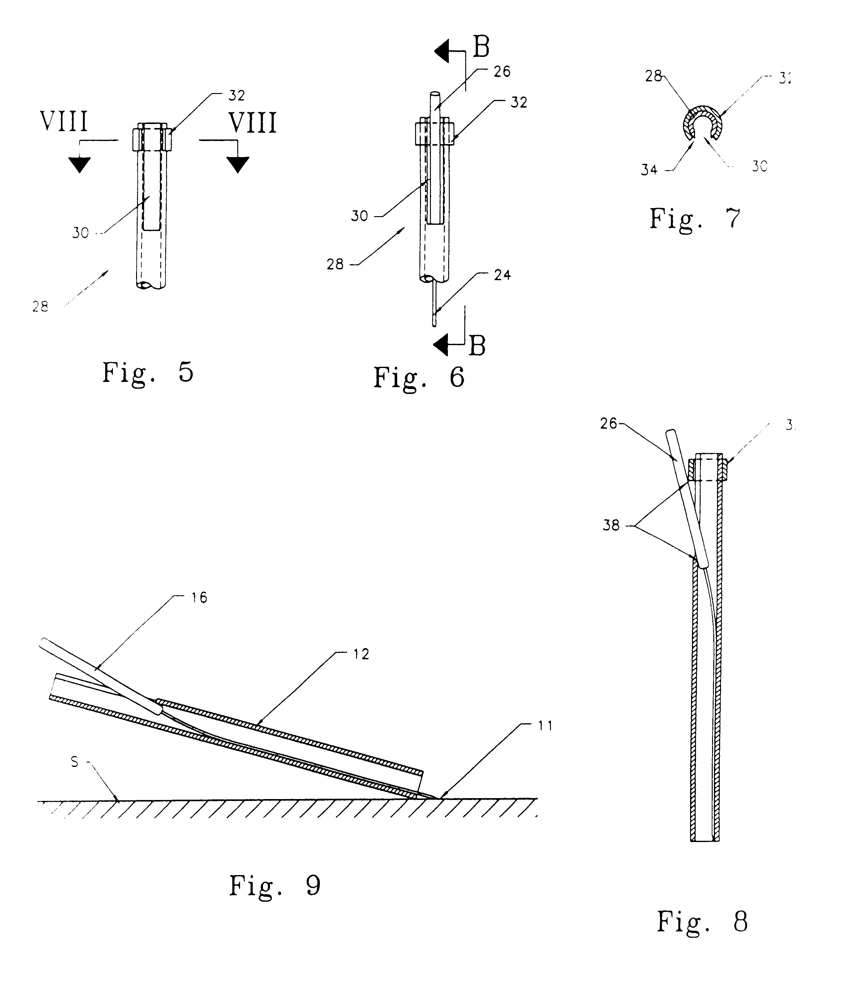
An acupuncture device of the invention is shown in FIGS. 2 and 4, where FIG. 2 is a side sectional view of the device and FIG. 4 is a view of the device of FIG. 2 in the direction of arrow A. The device as a whole is designated by reference numeral 15. It consists of a guide tube 12 and an acupuncture needle 14 with a needle handle 16. Since the needle 14 with the handle 16 is longer than the guide tube 12, the upper end of the handle 16 projects from the upper end of the guide tube.

The upper end of the guide tube 12 has a slot or notch (FIG. 4) which may be a triangular shape notch 20 shown in FIG. 4, or a rectangular shape notch 18 shown in FIG. 3. When there is a rectangular notch 18, the width of the notch 18 should slightly exceed the diameter of the needle handle 16 in order to ensure free movement of the needle handle 16 inside the notch 18. The slot or notch may have a depth of 12 mm or more.

As can be seen from FIG. 2 or FIG. 4, the upper edge of the guide tube 12 can be cha...


PUM


Abstract

An acupuncture device consists of an acupuncture needle and a guide tube having a longitudinal slot or notch at the upper end of the tube, which is wider than the diameter of the needle handle. A practitioner can easily secure the upper portion of the handle in this notch by pressing on the handle of the needle with an index finger. In the case of angular insertions, the practitioner can maintain a desirable diagonal position of the needle inside the guide tube. The acupuncture operation is facilitated by making a larger portion of the needle handle projecting from the guide tube through the notch. According to another embodiment, the device is provided with a sleeve of a C-shaped configuration, which is fit onto the upper end of the guide tube. When the open part of the C-shaped configuration does not coincide with the aforementioned notch, and the handle of the needle stays inside the guiding tube, the whole device can be used in a conventional fashion. When the open part of the C-shaped configuration coincides with the aforementioned notch, the needle handle can be pushed through the notch, and when the sleeve is turned so that the groove is overlapped, the needle handle will be deflected and fixed between the lower edge of the sleeve and the bottom of the notch.

Description

The present invention relates to the field of needle therapy, in particular to an acupuncture device with an improved needle guide tube.Acupuncture guide tubes are widely used in the practice of acupuncture to minimize discomfort during needle insertion. The guide tube allows quick insertion of an acupuncture needle through the epidermis. An example of a guide tube is the one shown in U.S. Pat. No. 5,792,171 issued in 1998 to Burdenko, et al. Fast puncturing of the patient's skin is important for pain-free insertion. There is typically 3-5 mm clearance between the upper end of the guide tube and the top of the handle of an acupuncture needle, which protrudes above the tube. The practitioner taps on the handle of the needle downward with his / her index finger while supporting the tube with the other hand. The needle, which has been resting on the surface of the patient's skin prior to insertion, is now inserted 3-5 mm through the skin into the acupuncture point. The guide tube has a d...

Claims


Application Information

Patent Timeline
IPC IPC(8): A61H39/00A61H39/08A61B17/34
CPCA61H39/08A61B2017/3405Y10S128/907
Inventor GAVRONSKY, STAS
Owner GAVRONSKY STAS
Why Eureka
Try Eureka