Tool for applying mortar

Inactive Publication Date: 2014-10-30
JONES PETER ANTHONY +1
View PDF4 Cites 2 Cited by
  • Summary
  • Abstract
  • Description
  • Claims
  • Application Information

AI Technical Summary

Benefits of technology

The invention aims to allow for a quick and uniform bed of mortar to be created, and to make the process of pointing the mortar easier. This is compared to conventional techniques.

Problems solved by technology

The process of laying and levelling the bed of mortar, and pointing are time consuming and require skill to perform well.

Method used


Image

  • Tool for applying mortar
  • Tool for applying mortar
  • Tool for applying mortar

Examples


Embodiment Construction

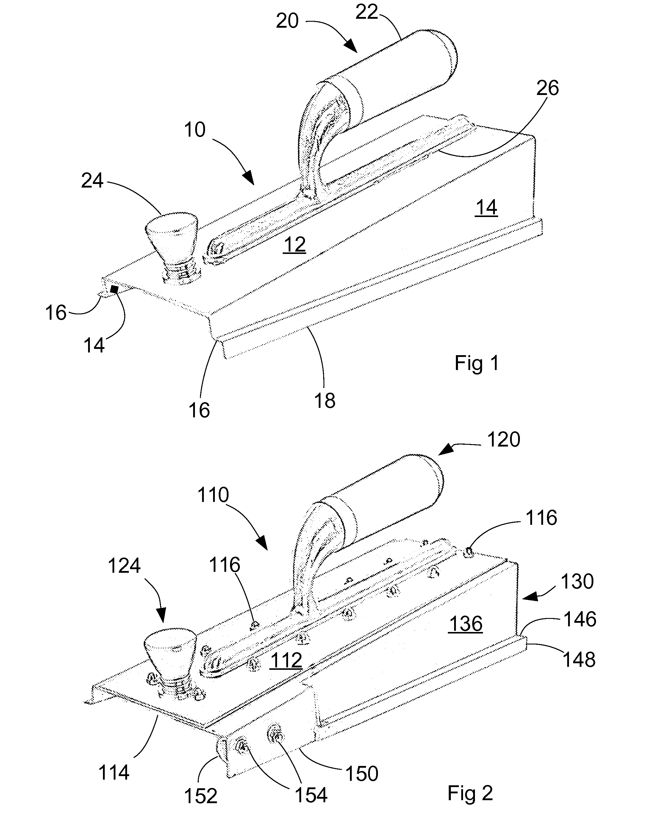
[0023]A first embodiment of the invention will now be described with reference first to FIG. 1.

[0024]The tool embodying the invention has a body 10 that is formed from a durable material, typically sheet stainless steel. The body 10 is formed with a generally planar, rectangular top panel 12 that has two long edges and two short edges. A respective spaced, parallel side wall 14 extends from each long edge at a right angle with the top panel 12. Each side 14 wall is shaped as a right-angled trapezium, with three sides at 90° to one another and a fourth side, which adjoins a long edge of the top panel 12. The fourth side extends at an angle of approximately 10°. Thus, when the fourth sides are placed on a level surface, the top panel 12 slopes with respect to that surface, whereby wedge-shaped chamber of an inverted, square U-shaped cross-section is defined below the top panel 12. The uppermost surface of the top panel 12, when in this position, will be referred to as its upper surfac...


PUM


Abstract

A tool for spreading mortar in laying bricks or blocks and a method for using such a tool are disclosed. The tool comprises a body that has a long axis, wherein transverse to the long axis, the body has a cross-section that defines a chamber under a flat upper wall and between side walls, the chamber having a height that decreases from a leading edge to a trailing edge of the upper wall. In the method, the tool is placed such that the chamber substantially spans the layer of mortar, and moving the tool along the layer of mortar with the leading foremost while applying a force to the tool in a direction substantially normal to the upper wall, whereby the mortar layer is formed into a mortar bed.

Description

BACKGROUND TO THE INVENTION[0001]1. Field of the Invention[0002]This invention relates to a tool for applying mortar. It has particular application to a tool to assist in construction using bricks or blocks. The term “blocks” will be used in this specification to refer to all types of building construction unit, including, but not limited to bricks and blocks of concrete.SUMMARY OF THE PRIOR ART [0003]During construction of a wall of blocks, a bricklayer places a bed of mortar on top of a footing or a previously laid course of blocks. A course of blocks are then placed upon the bed of mortar, and these have to be pushed or tapped down to the correct height to align the newly laid blocks and to form a consistent bed of mortar between the courses of blocks.[0004]With this method of bricklaying, excess mortar can run down the face of the blocks or fall into a cavity between leaves of a cavity wall. The mortar between the blocks on the face side of the wall (that is, the side of the wal...

Claims


Application Information

Patent Timeline
IPC IPC(8): E04F21/16B05D1/40
CPCB05D1/40E04F21/161E04G21/201E04G21/204
Inventor JONES, PETER ANTHONYJONES, CARL ANTHONY
Owner JONES PETER ANTHONY
Why Eureka
Try Eureka