Expansion mediated adhesive device

Pending Publication Date: 2021-11-04
BVW HLDG
View PDF0 Cites 0 Cited by
  • Summary
  • Abstract
  • Description
  • Claims
  • Application Information

AI Technical Summary

Benefits of technology

The patent text describes a microstructure surface with certain properties that make it difficult for liquids to spread on the surface. This results in a lower energy surface that resistant to translocation. The microstructure surface can be repositioned during a surgical procedure, making it easier to place and adjust the device. This allows for greater flexibility and minimizes the invasiveness of the surgery. Overall, the invention provides a better method for adhesion in medical applications.

Problems solved by technology

Because of a liquid and solid phase construction, it can be difficult to have one surface adhere to another surface when a liquid phase is acting as a lubricant or repulsive barrier.
For example, surgical meshes that are used as medical implants can be difficult to fixate on an organ because of interstitial fluid.
However, a major drawback of such utilization is the physical damage that can be caused to the underlying tissue.
Piercing tissue to fixate a medical implant can cause unwanted side effects such as inflammation, swelling, scarring, as well as the possibility of ripping the sutures from the underlying tissue then causing even further damage.

Method used


Image

  • Expansion mediated adhesive device
  • Expansion mediated adhesive device
  • Expansion mediated adhesive device

Examples


example 1

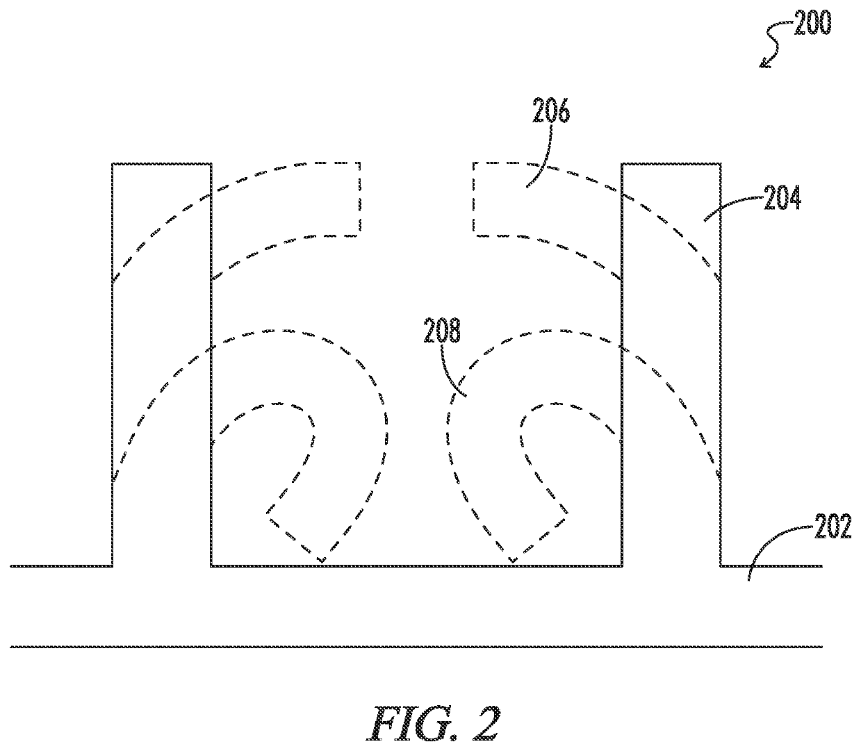
[0103]Referring to FIG. 2, an expansion mediated adhesion device 200 may include a non swellable substrate 202 on which may be printed or cast a swellable microstructure 204. Printing techniques are well known in the art. The casting technique may involve forming the substrate 202 and microstructure 204 by coating one side of the substrate with a curable swellable polymer and then sandwiching against the mold the curable polymer between the substrate and the mold. The mold may be manufactured to produce the microstructure 204 from the curable swellable polymer. Microstructure 204 may be a cylindrical pillar of 10 to 1000 microns, preferably 50 to 200 microns, with a pitch of between 10 microns and 100 microns, and a diameter of 10 to 50 microns. Due to edge effects, the center of the pillar may be more densely cross linked then the exterior surfaces.

[0104]When the microstructure is exposed to water, or some other liquid, the outer surface may swell more than the interior causing the...

example 2

[0105]Referring to FIG. 3, an expansion mediated adhesion device 300 may include substrate 302, first swellable microfeature 304, 310 on which is arranged hierarchically a second non-swellable microfeature 306. Upon non-swellable microfeature 306 may be arranged a third non-swellable microfeature 308. When the first swellable microfeature 304, 310 swells it may obtain a swollen geometry 312 as depicted by the dashed line. The second microfeature 306 of adjacent microstructures may be displaced toward one another at an intersecting position 314 via the swelling of the first microfeature 304, 310. When two adjacent second microfeatures 306 come together, a pincer motion may be generated which may be capable of grasping a surface placed in the vicinity of device 300.

example 3

[0106]Referring to FIG. 4, an expansion mediated adhesion device 400 may include substrate 402 and non-swellable first microfeature 404. A second swellable microfeature 406 may be disposed about the substrate 402 adjacent the first microfeature 404. The spacing of the first 404 and second microfeature 406 may generate a hydrophilic surface energy that draws a target layer into a domain region 408. If the target substrate is fibrous, then fiber(s) may fill the domain region 408. Fluid on the surface of the target surface may cause the second microfeatures 406 to expand. The surfaces 410 of the polymerized polymer of the second microfeatures 406 may include a highly crosslinked skin. This skin surface 410 may produce an effect common to many crosslinking polymers. The expansion rate and capacity of the skin surface 410 may be less than the interior portion 412. This may cause the second microfeature 406 to bend as depicted by dashed lines 414. The bending direction may be random or ma...


PUM

PropertyMeasurementUnit
Diameteraaaaaaaaaa
Diameteraaaaaaaaaa
Heightaaaaaaaaaa

Abstract

An adhesive device comprising a microstructure and polymer designed to interdigitate with the surface structure of a target surface. The device may include a microstructure material having an elastomeric, crosslinked polymer which may swell in the presence of a liquid. In the pre-swell state, the device microstructure may interdigitate with a target surface microstructure. When liquid on the target surface contacts the microstructure surface of the device, the liquid may cause the microstructure surface of the device to swell. The swelling may cause the microstructure to grasp the target surface resulting in adhesion between the device and the target surfaces.

Description

CROSS-REFERENCES TO RELATED APPLICATIONS[0001]This application claims benefit of the following patent application(s) which is / are hereby incorporated by reference: 63 / 019,932 filed on May 4, 2020.[0002]A portion of the disclosure of this patent document contains material that is subject to copyright protection. The copyright owner has no objection to the reproduction of the patent document or the patent disclosure, as it appears in the U.S. Patent and Trademark Office patent file or records, but otherwise reserves all copyright rights whatsoever.STATEMENT REGARDING FEDERALLY SPONSORED RESEARCH OR DEVELOPMENT[0003]Not ApplicableREFERENCE TO SEQUENCE LISTING OR COMPUTER PROGRAM LISTING APPENDIX[0004]Not ApplicableBACKGROUND OF THE INVENTION[0005]The present invention relates generally to an adhesive device which contains a crosslinked polymer microstructured surface obtained by the polymerization of specific monomers while in contact with a microstructured mold. The device may exhibit...

Claims


Application Information

Patent Timeline
IPC IPC(8): C09J9/00B81B3/00
CPCC09J9/00B81B2207/99B81B3/0089C09J7/00C09J2301/31C09J2301/10C09J2301/30C09J2400/22C09J2433/00C09J2433/006
Inventor BLUECHER, LUKASMILBOCKER, MICHAEL
Owner BVW HLDG
Why Eureka
Try Eureka