
Field repairable hermaphroditic connector

Inactive Publication Date: 2001-05-22
STRATOS INT
View PDF12 Cites 475 Cited by
  • Summary
  • Abstract
  • Description
  • Claims
  • Application Information

AI Technical Summary

Benefits of technology

It is still yet another object of the invention to provide a termination device which has a low insertion loss when coupled with another termination device.
It is still another object of the invention to provide a termination device which is inexpensive to manufacture and assemble.
Thus, Applicants' invention provides a termination device which is compact, easy to repair, scoop proof, hermaphroditic, inexpensive to manufacture and assemble, blind mateable, and which has a low insertion loss. These and other features of the invention are set forth below in the following detailed

Problems solved by technology

A breakdown of communications can result in disaster.
Another problem with communication lines is that slow or small amounts of transferred data is akin to no communication what-soever.
A fiber optic cable can not be easily tapped as an electrical wire since optical signals do not induce electromagnetic fields as does an electrical wire conducting electricity.
Furthermore, the fiber optic cable has a large bandwidth; that is, it conveys large amounts of information per unit time.
However, expanded beam termination devices have a downside, the insertion loss is relatively high.
The insertion loss is high due to expanding the light beam.
The expanding light beam is partially scattered and lost, thus, the signal looses power at each union of termination devices.
The insertion loss prevents a number of the optical cables from being ganged together since the signal would eventually be lost at the end of the last optical cable; i.e., there would be no usable light energy emanating from the cable.
Therefore, the distance between signal transmitting and signal receiving devices is limited unless expensive, cumbersome, power boosting, relay equipment is connected to the optical cable between the transmitting and receiving devices.
Another downside of expanded beam connector termination devices is that once the termination device becomes so fouled with environmental or other debris, it is very difficult, if not impossible, to clean and / or fix the termination device.
However, even ordinary battlefield rigors and debris may take their toll on one or many termination devices thus necessitating their repair or replacement.

Method used


Image

  • Field repairable hermaphroditic connector
  • Field repairable hermaphroditic connector
  • Field repairable hermaphroditic connector

Examples


Embodiment Construction

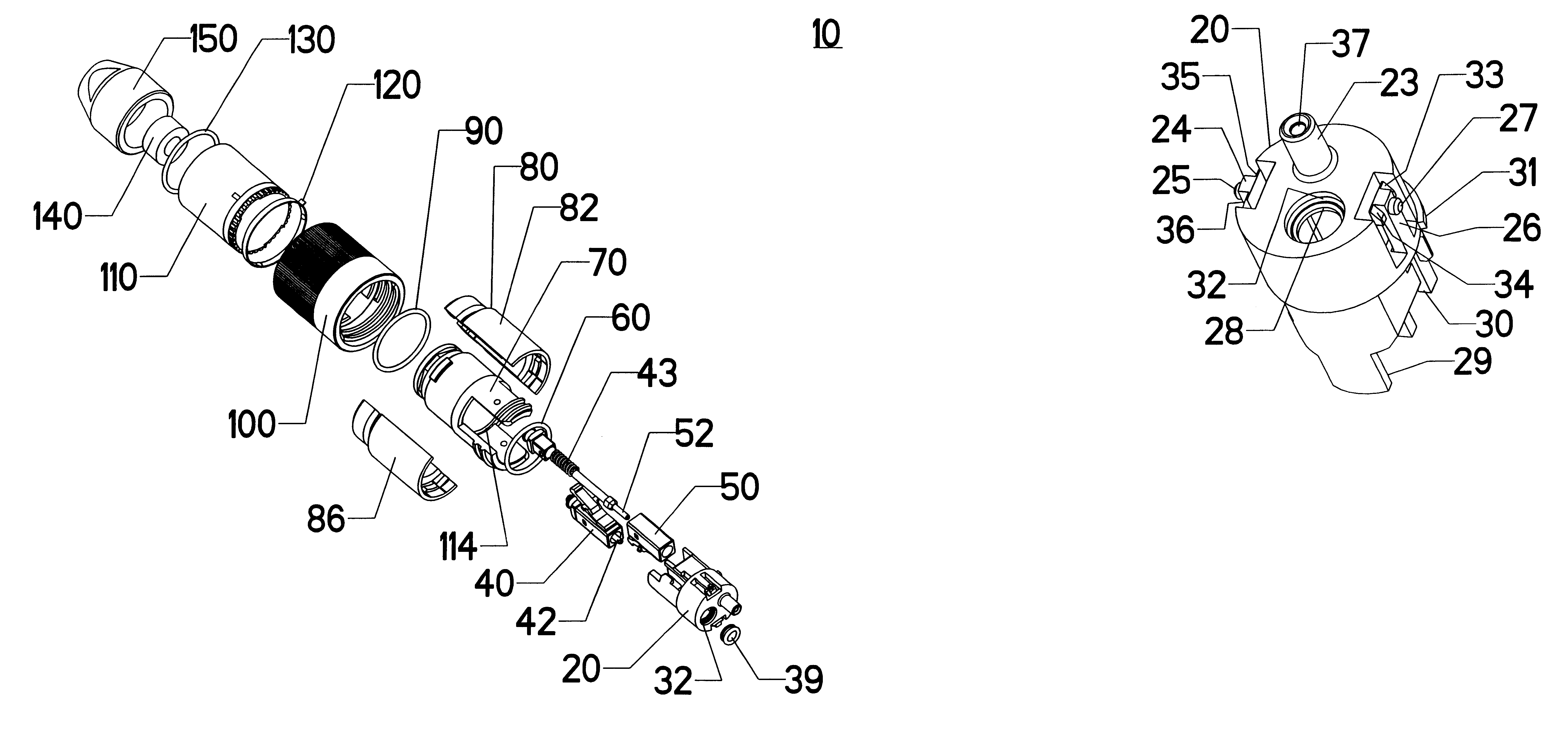
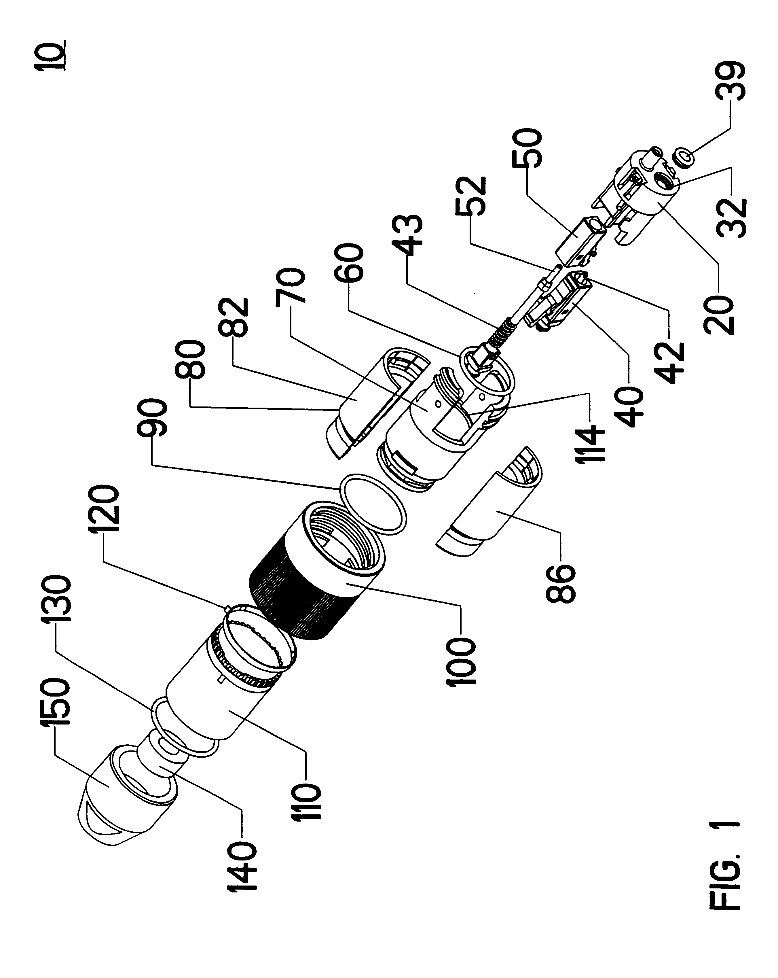
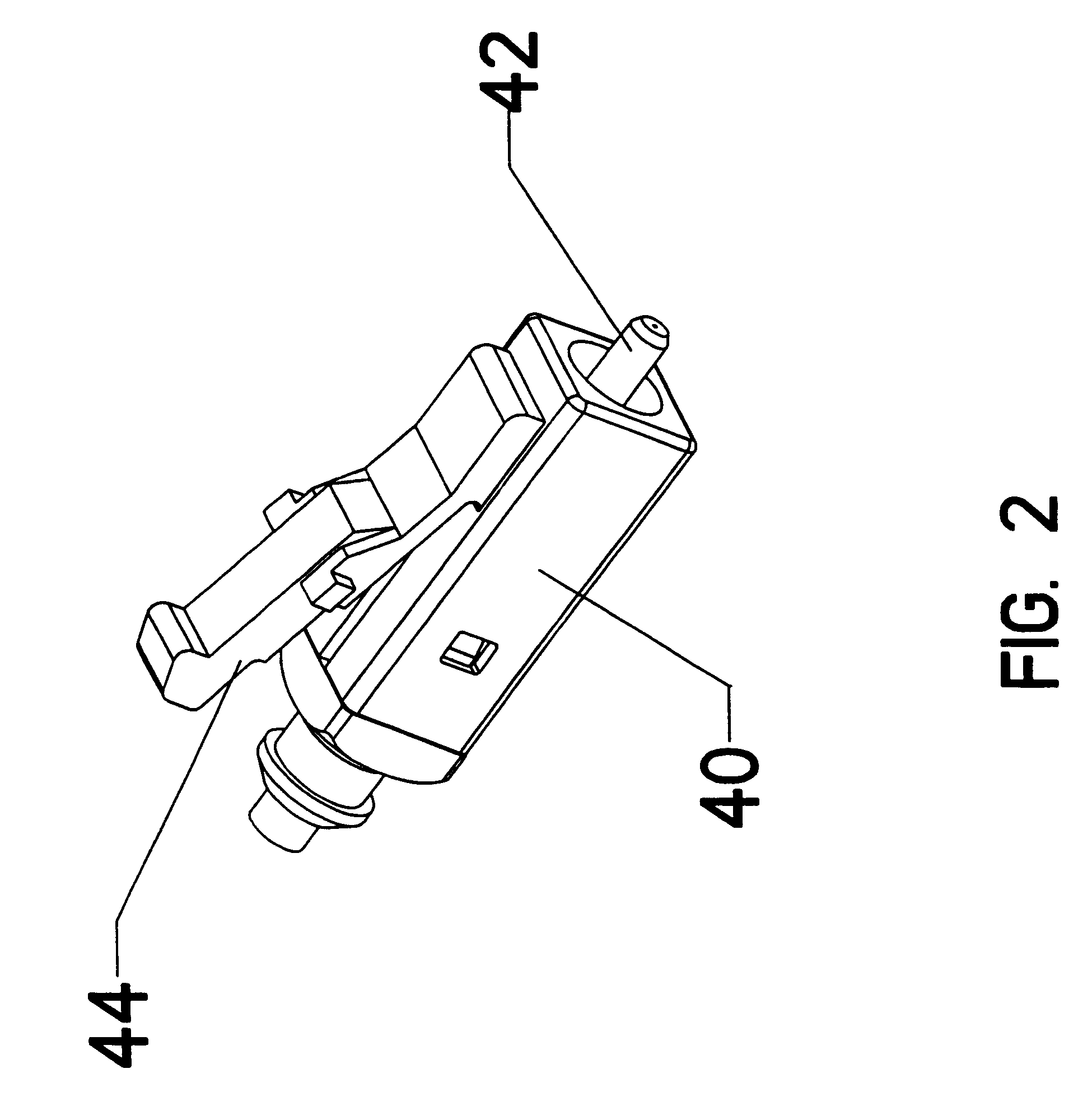
Referring now to the drawings, wherein like reference numerals designate identical or corresponding parts throughout the several views, and more particularly to FIGS. 1-11 thereof, a first embodiment of the present new invention is a termination device 10.

FIG. 1 is an exploded, perspective view of the hermaphroditic termination device 10. The termination device 10 includes a housing 70, a plug insert 20, fiber optic connectors or assemblies 40, 50, an extension sleeve 80, a grip ring 100, a cover tube 110, a click ring 120, a cable seal 140, a back end plug 150, and associated seals 39, 60, 90, 130. As can be seen, the fiber optic assemblies or connectors 40 and 50 are removeably insertable into the plug insert 20. Likewise, the plug insert 20, containing the fiber optic assemblies 40 and 50, is insertible into the housing 70. Not shown in FIG. 1 are the optical fibers associated with an optical cable and a crimp sleeve (see FIG. 3). At the time of the assembly, each of the fiber op...


PUM


Abstract

A hermaphroditic fiber optic termination device including a plug insert removably insertable into a front of a housing. The housing having locking holes. The plug insert formed so as to receive ferrules surrounding terminal ends of the optical fibers. The plug insert having spring latches, where each spring latches has a nub. The nub feature being designed so as to spring into the locking holes of the housing.

Description

1. Field of the InventionThe present invention pertains to a termination of a fiber optic cable or waveguide. The invention more particularly concerns a termination that takes the form of a field repairable hermaphroditic connector.2l . Discussion of the BackgroundPresently, the control of fast, secured communication translates into power. Thus, secured communication lines are a highly valued commodity. Perhaps no where is the need for secured communications so desired as it is on the battlefield. Communication lines transmit data to coordinate the individual components of a larger unit. Communication lines transmit logistical data. Communication lines transmit data concerning the positions of enemy targets. Communication lines transmit data concerning strategic and tactical placement of ordinance and personnel. A breakdown of communications can result in disaster. Throughout history, effective communications have prevailed as a key element to successful military engagement.In the p...

Claims


Application Information

Patent Timeline
IPC IPC(8): G02B6/38
CPCG02B6/383G02B6/3869G02B6/3878G02B6/3894G02B6/3821G02B6/3831G02B6/3849G02B6/3887G02B6/3898G02B6/3888G02B6/38
Inventor WALDRON, MARK R.CROCKER, MARTINFICK, PHILIPHAGGER, ALAN
Owner STRATOS INT
Learn More