Magnetic metal sensor and method for detecting magnetic metal

a magnetic metal and sensor technology, applied in the field of magnetic metal sensors, can solve the problems of low response rate of the magnetic metal sensor of the eddy current system, difficult to detect metal pieces of small sizes, and difficult to detect metal pieces moved at an elevated speed

Inactive Publication Date: 2001-05-22
DMG MORI SEIKI CO LTD
View PDF1 Cites 34 Cited by
  • Summary
  • Abstract
  • Description
  • Claims
  • Application Information

AI Technical Summary

Problems solved by technology

Meanwhile, the magnetic metal sensor of the eddy-current system is usually low in response rate.
Thus, with the magnetic metal sensor of the eddy-current sensor, it has been difficult to detect a metal piece moved at an elevated speed or plural metal pieces paced side-b-side.
Thus, with the magnetic metal sensor of the eddy current system, it has been difficult to detect metal pieces of small sizes.
In addition, with the eddy-current type magnetic metal sensor, since t

Method used


Image

  • Magnetic metal sensor and method for detecting magnetic metal
  • Magnetic metal sensor and method for detecting magnetic metal
  • Magnetic metal sensor and method for detecting magnetic metal

Examples


first embodiment

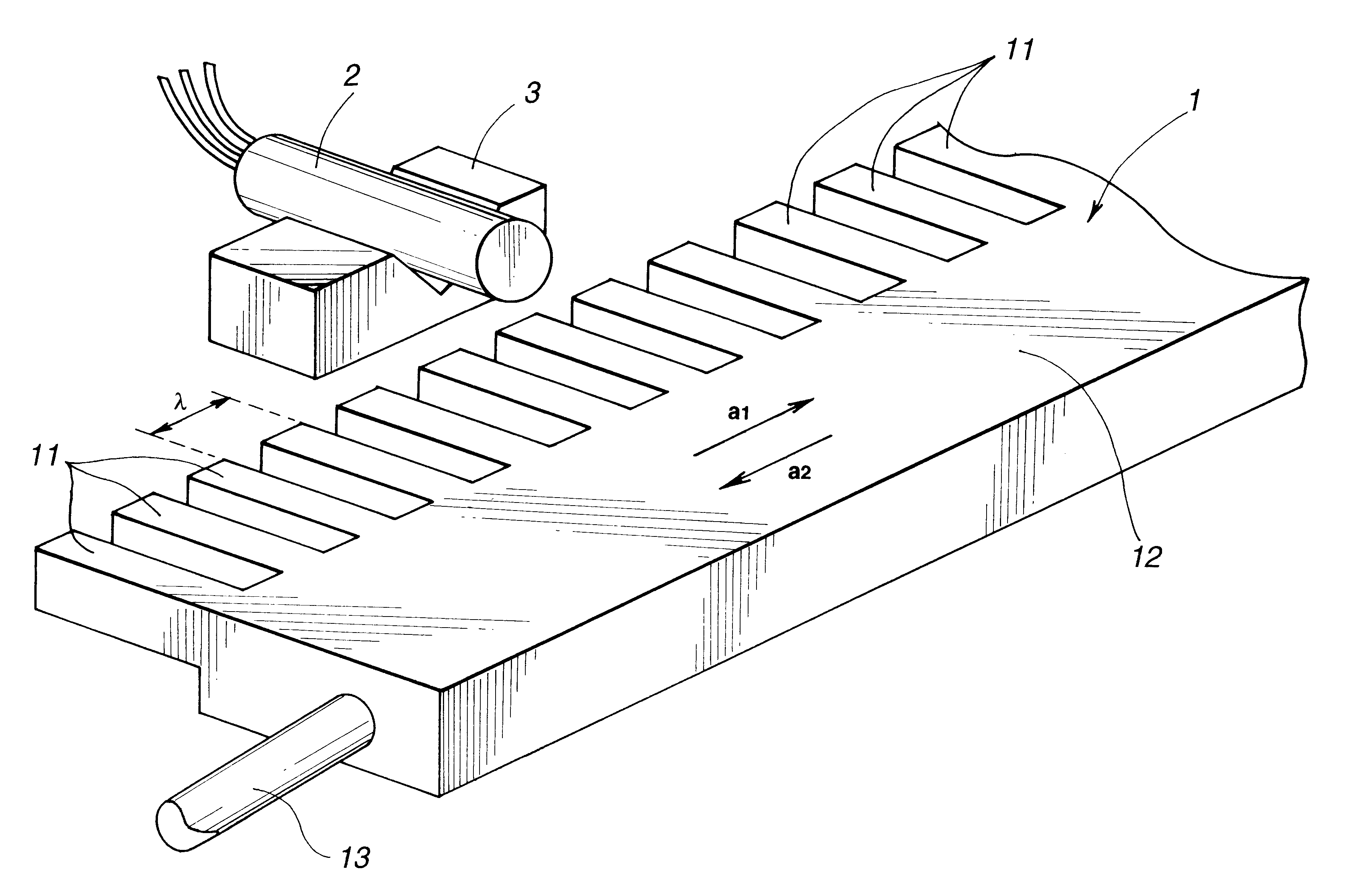
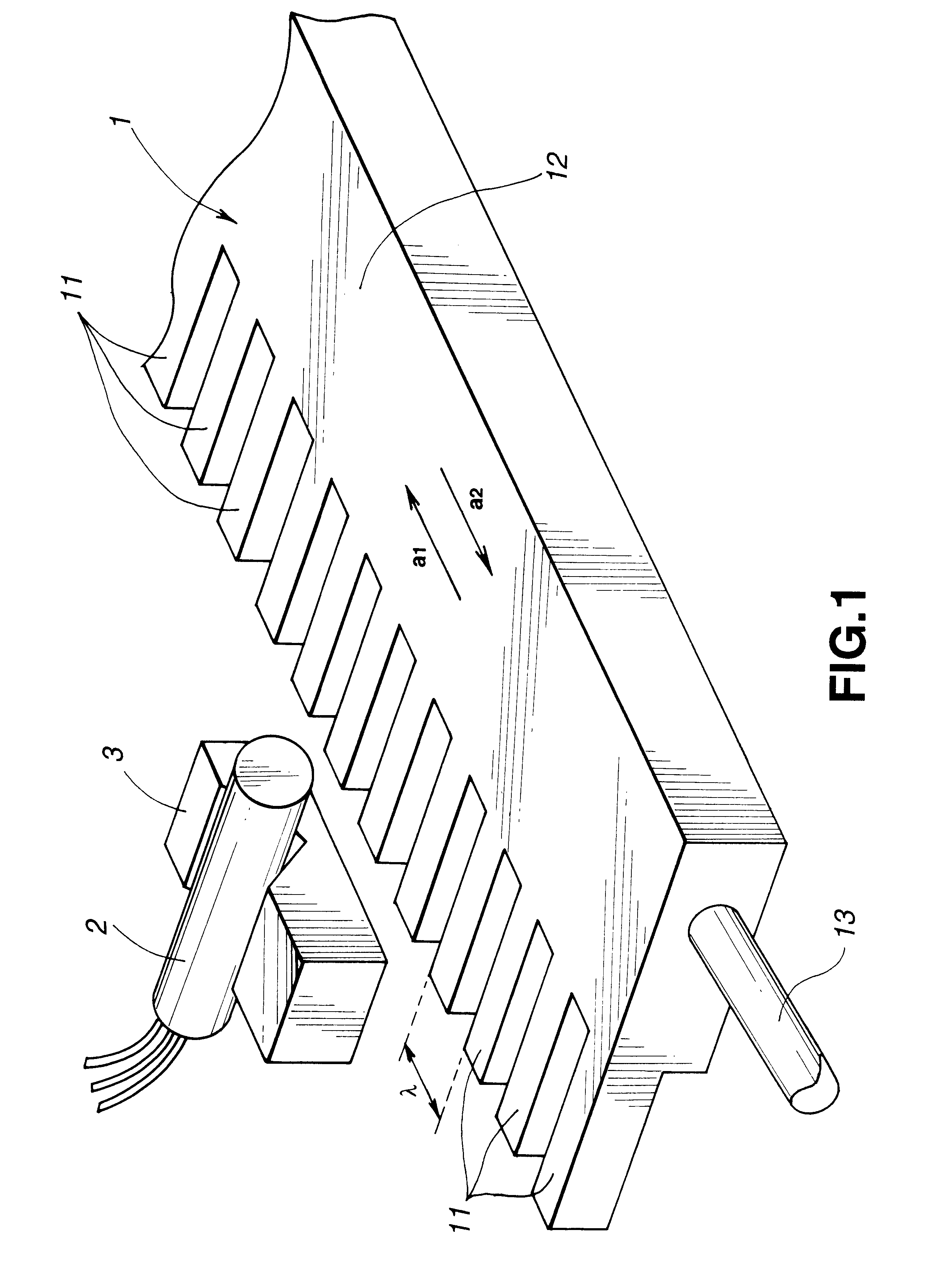
FIG. 1 shows a perspective view of a metal piece counter employing a magnetic metal sensor of the present invention. This metal piece counter detects the position of movement of a member under detection having its plural magnetic metal pieces arranged side-by-side at pre-set separation from one another.

Referring to FIG. 1, the metal piece counter is made up of a member under detection 1 and a magnetic metal sensor 2 secured to a sensor support block 3.

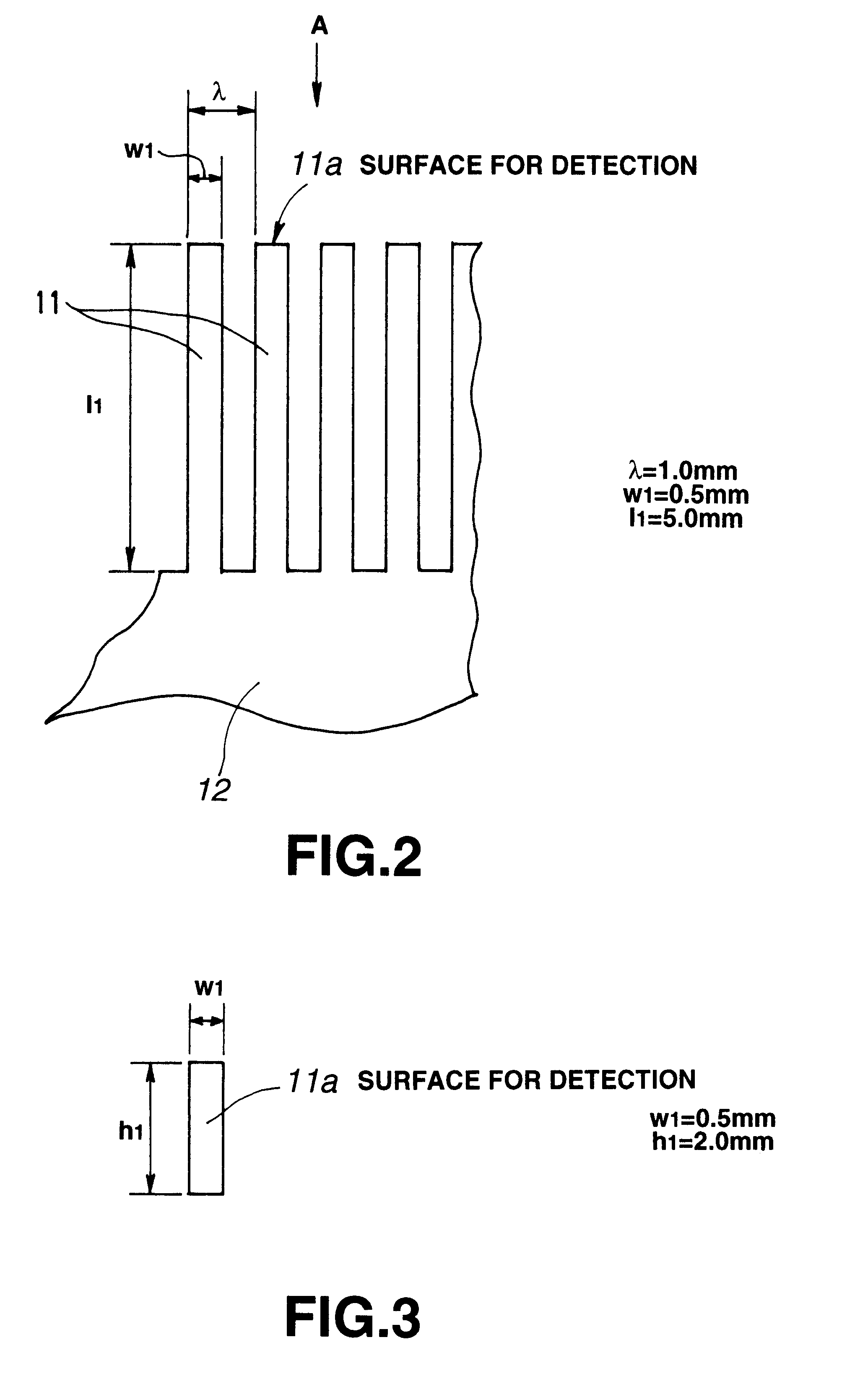
The member under detection 1 includes a plurality of metal pieces 11 arrayed side-by-side at a pre-set separation .lambda. from one another. These metal pieces 11 are formed of magnetic metal, such as iron, and are parallelepipedic in shape. These metal pieces 11 have one longitudinal ends secured to an indicator 12 to constitute together the member under detection 1.

Referring to the plan view of FIG. 2 and the side view of FIG. 3 looking from the direction A of FIG. 2, the length l1, width w1 and the height h1 of each metal piece 11 a...

second embodiment

the magnetic metal sensor of the present invention is hereinafter explained. The parts and components which are the same as those of the first embodiment are depicted by the same reference numerals and the corresponding description is omitted for simplicity.

First, the magnetic metal sensor of the second embodiment, applied to a metal piece counter for detecting the movement position of the member under detection having the magnetic metal pieces arrayed side-by-side in a pre-set separation from one another, is explained with reference to the drawings.

FIG. 14 shows a perspective view showing a metal piece counter.

The metal piece counter is made up of a member under detection 1 and a magnetic metal sensor 40 secured to the sensor mounting block 3.

FIG. 15 shows the structure of the magnetic metal sensor 40.

The magnetic metal sensor 40 is comprised of a magnetically sensitive unit having a substantially U-shaped open magnetic circuit type core 22, about which saree wrapped coils 23 and 2...


PUM


Abstract

A magnetic metal sensor having a high response speed and which can detect small-sized metal pieces and can elongate the separation from the metal pieces. A magnetic metal sensor 2 has a core 22 defining a substantially U-shaped open magnetic path and coils 23, 24 of the same polarity mounted on the core 22. A uniform magnetic field along the direction of magnetic sensitivity is applied by a magnet 25 across the coils 24, 24. If magnetic metal approaches to a open magnetic path portion of the core 22 of the magnetic metal sensor 2, the magnetic reluctance of the magnetic circuit formed by the core and air is changed, as a result of which the impedance of the cores 23, 24 is changed. The magnetic metal sensor 2 detects the possible presence of magnetic metal or its displacement based on impedance changes of the paired coils 23, 24.

Description

1. Field of the InventionThis invention relates to a magnetic metal sensor for detecting a magnetic metal piece and a method for detecting magnetic metal using the magnetic metal sensor. As an example, the present invention relates to a magnetic metal sensor for detecting the possible presence of a magnetic metal piece or its displacement, a magnetic metal sensor for detecting a plurality of magnetic metal pieces from a unit under detection comprised of the magnetic metal pieces arranged side-by-side at a pre-set separation from one another.2. Related ArtThere has hitherto been known an eddy-current type sensor as a magnetic metal sensor for detecting the possible presence or displacement of magnetic metal.This type of the magnetic metal sensor is desired to be used in a system, such as a machine tool for detecting the number of teeth of a gear for controlling the rpm of the rotational angle of the gear, or in a system for detecting the number of teeth used for knitting fibers in a ...

Claims


Application Information

Patent Timeline
IPC IPC(8): G01V3/10
CPCG01V3/105H03K17/9505
Inventor NEKADO, YASUOKUSUMI, MASAAKI
Owner DMG MORI SEIKI CO LTD
Why Eureka
Try Eureka