Loop antenna assembly for telecommunication devices

a technology of telecommunication devices and loop antennas, applied in the structural form of loop antennas, resonant antennas, radiating elements, etc., can solve the problems of limited signal range, limited directionality, and may be more susceptible to damag

Inactive Publication Date: 2001-05-22
TYCO ELECTRONICS LOGISTICS AG (CH) +1
View PDF21 Cites 69 Cited by
  • Summary
  • Abstract
  • Description
  • Claims
  • Application Information

AI Technical Summary

Problems solved by technology

It is recognized that prior art monopole antennae, while providing good radiation characteristics and desirable drive point impedance, may be more subject to damage than a compact antenna protected within the interior of the transceiver hous...

Method used


Image

  • Loop antenna assembly for telecommunication devices
  • Loop antenna assembly for telecommunication devices
  • Loop antenna assembly for telecommunication devices

Examples


Embodiment Construction

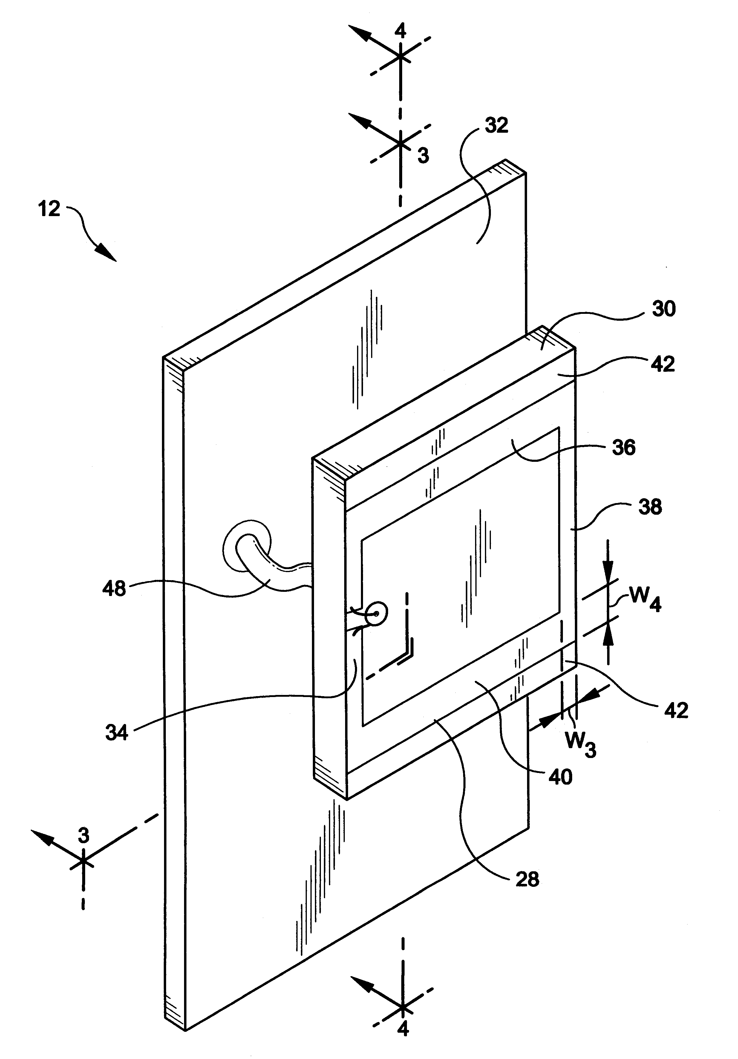
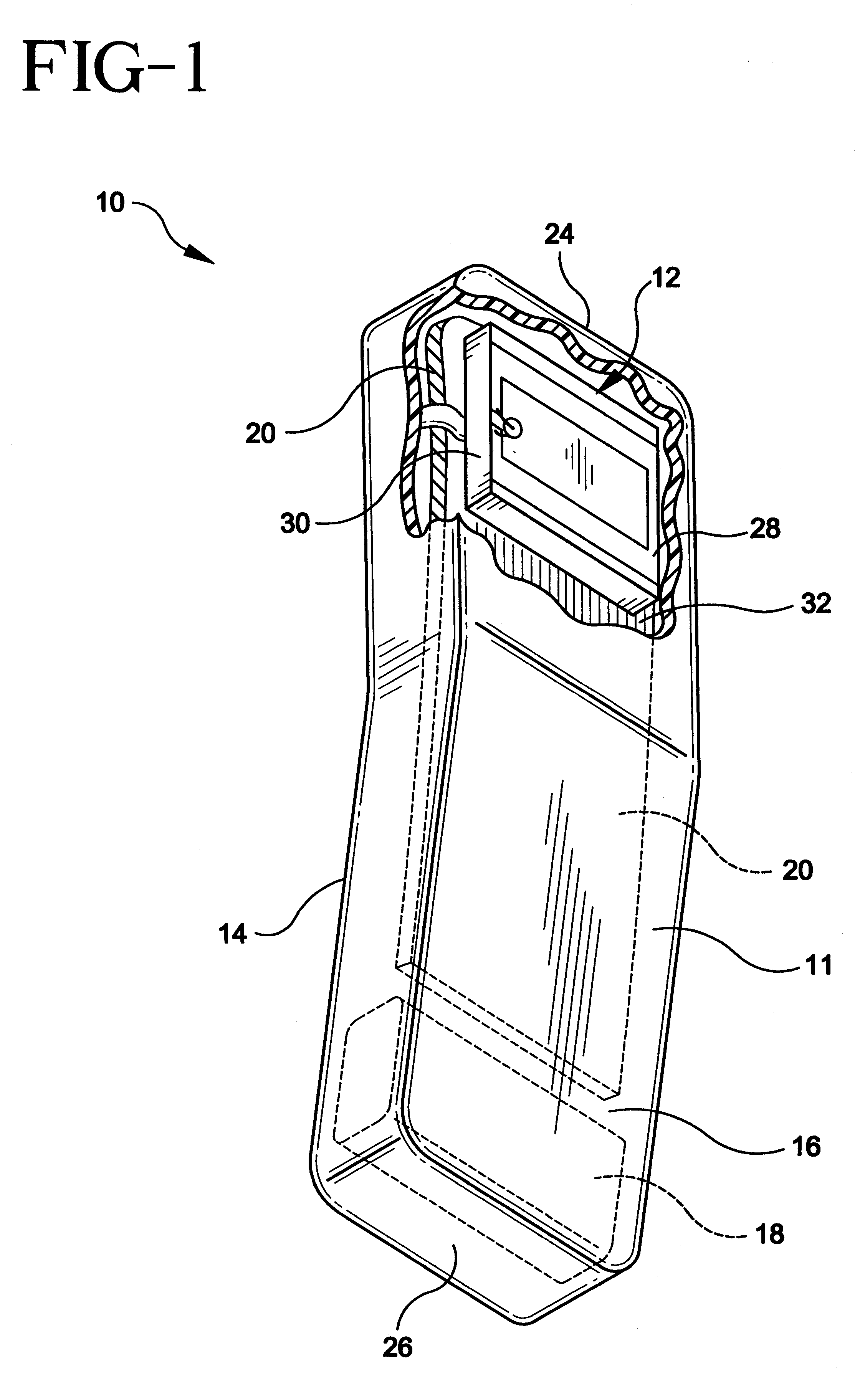
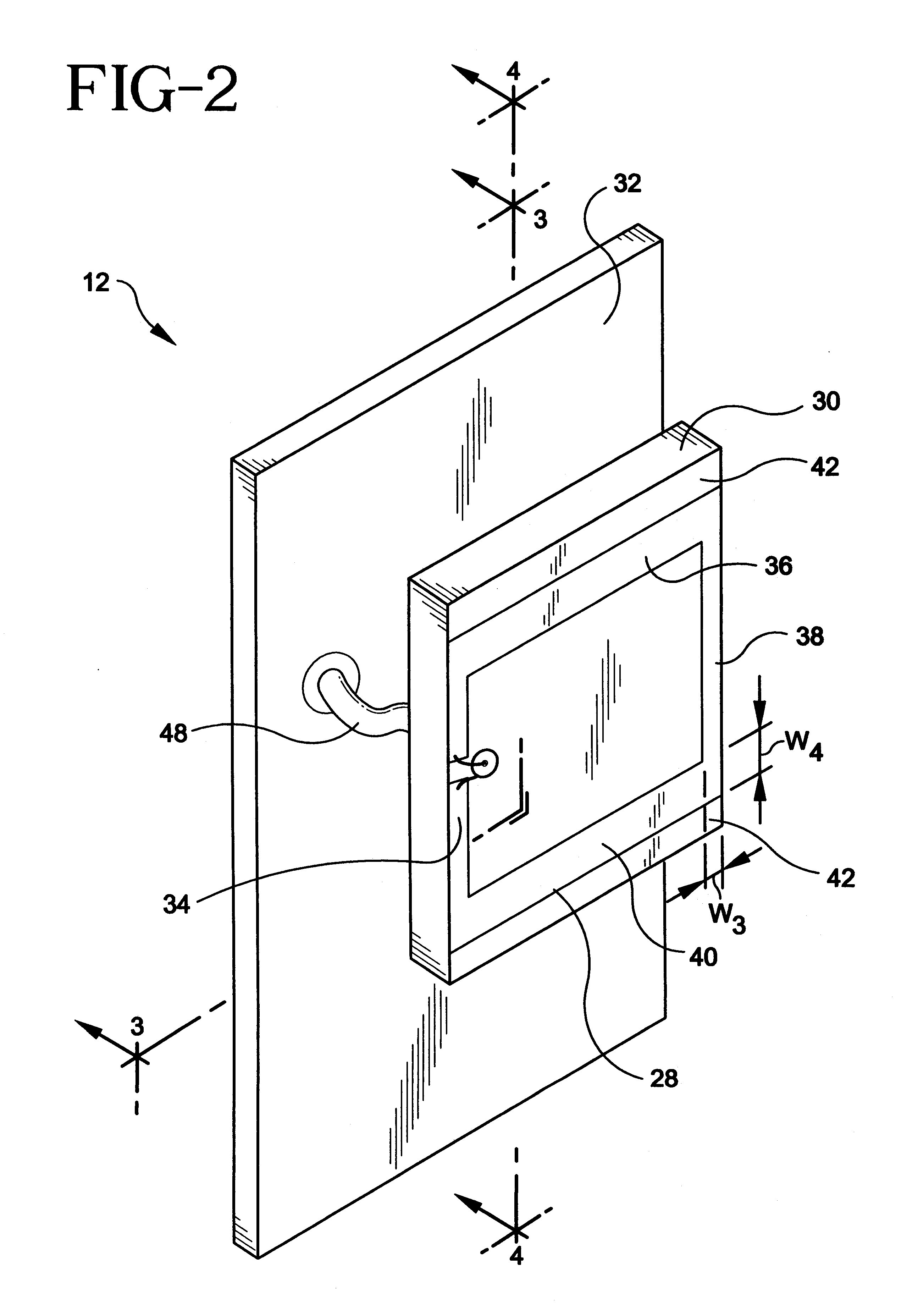
FIG. 1 illustrates a perspective view of a hand-held cellular telephone handset 10 and antenna assembly 12. Telephone handset 10 includes a front side 14 having speaker and microphone (not shown) and a rear side 16. Handset 10 is electrically powered by a battery or battery pack 18. Handset 10 includes one or more printed circuit boards 20 used to receive components and route signals between the multiple electronic components. Printed circuit board 20 in this embodiment also establishes a ground plane 32 for the antenna assembly 12. Alternative ground planes 32 may also be incorporated into the antenna assembly 12 as described hereinafter.

Antenna assembly 12 is revealed in FIG. 1 through a partial break-away of the handset 10 housing 11. The housing 11 may be made of an electrically nonconductive material. Antenna assembly 12 is positioned nearer to the top 24 than the bottom 26 of the handset 10 so that a user's hand will normally be away from the antenna assembly 12. Immunity to h...


PUM


Abstract

A loop directive antenna having improved front-to-back ratio and gain for given input power levels assembly for a hand-held radio frequency transceiver, such as a cellular telephone or PCS device operating in the 800-900 or 1850-1990 MHz. frequency ranges, respectively, is provided by the present invention. The loop directive antenna assembly consists of a main loop antenna conductor disposed upon a dielectric element. The main loop antenna conductor and dielectric element are maintained a predetermined distance away from a ground plane, which may be the circuit board or other conductive element. The main loop antenna conductor may include a variety of feedpoint orientations to provide alternative polarizations of the transmitted signal. The ground plane may be a portion of the printed circuit board of the device, a conductive part of the device housing, the battery pack of the device, or a separate conductive panel.

Description

The present invention relates generally to an antenna assembly, and more particularly to a loop antenna assembly for a hand-held radio frequency transceiver, such as a cellular telephone or PCS device operating in the 800-900 or 1850-1990 MHz. frequency ranges, respectively.DESCRIPTION OF THE PRIOR ARTThere has been a recognized need for a compact antenna assembly for a hand-held radio frequency transceiver which offers increased performance in gain and front-to-back ratio at given input power levels. It is recognized that prior art monopole antennae, while providing good radiation characteristics and desirable drive point impedance, may be more subject to damage than a compact antenna protected within the interior of the transceiver housing.Performance limitations of many other prior antennas for radio frequency transceivers have included limited signal range, limited directionality, significant radio frequency radiation output to the user, and significant multipath interference.A ...

Claims


Application Information

Patent Timeline
IPC IPC(8): H01Q7/00H01Q1/24
CPCH01Q1/243H01Q7/00
Inventor JOHSON, GREG
Owner TYCO ELECTRONICS LOGISTICS AG (CH)
Why Eureka
Try Eureka