Process of manufacturing an electrical rotating actuator such as for use in weaving looms and weaving systems

a technology of rotating actuators and manufacturing processes, applied in the direction of manufacturing stator/rotor bodies, weaving, magnetic circuit shapes/forms/construction, etc., can solve problems such as overdimensioning of said looms

Inactive Publication Date: 2001-05-29
STAUBLI FAVERGES SA
View PDF17 Cites 11 Cited by
  • Summary
  • Abstract
  • Description
  • Claims
  • Application Information

AI Technical Summary

Problems solved by technology

This known type of device necessitates considerable power for moving the griffe frames, which power is furnished by the drive shaft of the weaving loom, this leading to said loom being overdimensioned.

Method used


Image

  • Process of manufacturing an electrical rotating actuator such as for use in weaving looms and weaving systems
  • Process of manufacturing an electrical rotating actuator such as for use in weaving looms and weaving systems
  • Process of manufacturing an electrical rotating actuator such as for use in weaving looms and weaving systems

Examples


Embodiment Construction

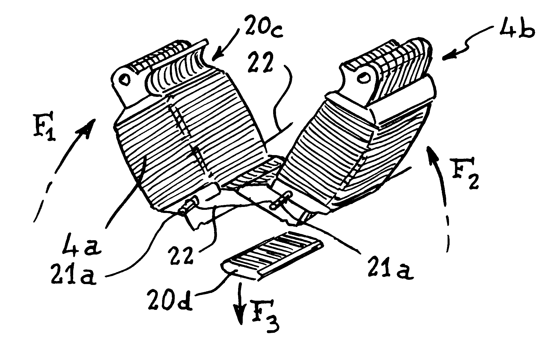
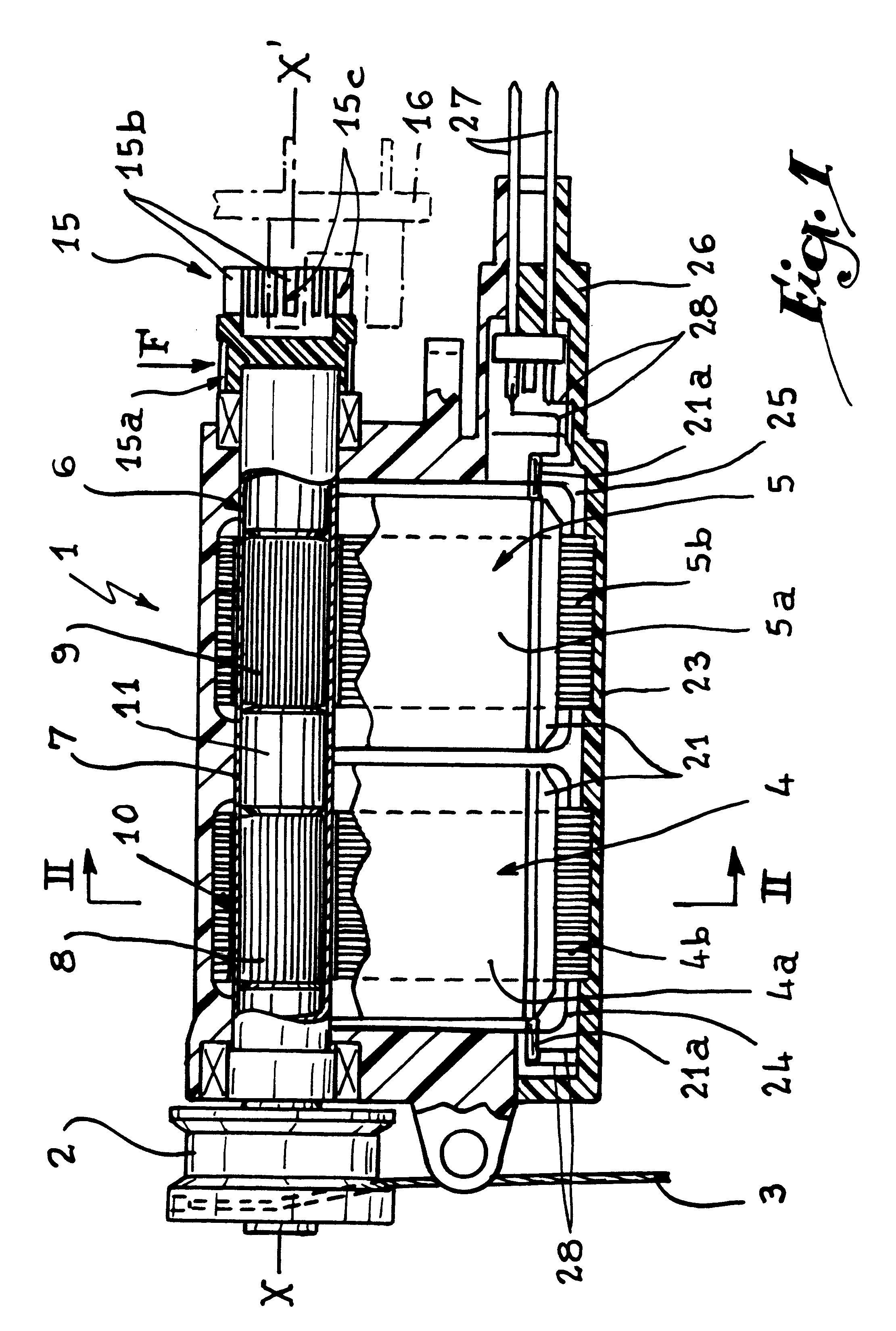
Referring now to the drawings and firstly to FIG. 1, the electrical rotating actuator 1 is intended to ensure the winding, on a pulley 2, of a harness cord 3 connected to one or more warp yarns of a weaving system of Jacquard type. The actuator 1 is a two-phase actuator. It comprises a stator formed by two stator elements 4 and 5 overall aligned along an axis XX' and adapted to cooperate with a rotor 6 formed by a tube 7 centered on an axis XX'. The tube 7 is preferably made of an a magnetic material, such as for example brass. The tube 7 contains two permanent magnets 8 and 9, disposed opposite the two stator elements 4 and 5.

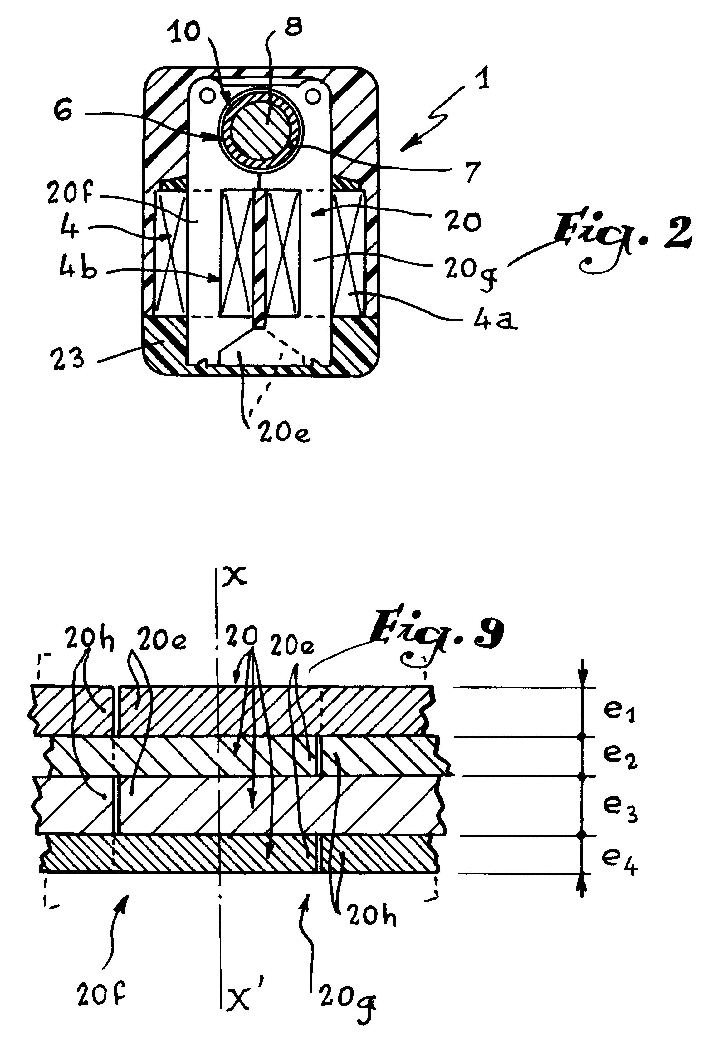
Elements 4 and 5 comprise windings 4a and 5a of electrically conducting wire, such as copper wire, wound around stacks 4b and 5b of magnetically conducting plates. The shape of the stacks 4b and 5b is such that they form a circular housing 10 for receiving the tube 7. The size of the housing 10 defines the air gap of the stator elements 4 and 5 with respect to...


PUM

PropertyMeasurementUnit
electrically conductingaaaaaaaaaa
sizeaaaaaaaaaa
poweraaaaaaaaaa

Abstract

A method of forming a stator for an electrical actuator of a type which may be used in weaving looms and weaving systems wherein a stack of armature plates having two-spaced sections are initially wrapped with an electrically conductive wire to create two coils afterwhich the stack is folded to sever severable bridge elements of the stack and to form an armature to include a tubular housing for a rotor.

Description

1. Field of the InventionThe present invention relates to an electrical actuator for forming the shed in a weaving loom, particularly for controlling the harness cords of a weaving system of the Jacquard type or the frames of a dobby, and to a process for manufacturing such an actuator. The invention also relates to a weaving system comprising such an actuator, and to a weaving loom equipped with such a system.2. Brief Description of the Related ArtIn weaving systems of the Jacquard type, it is known to drive, in phase opposition, two frames each bearing a plurality of griffes or horizontal knives 10 adapted to displace, vertically, hooks connected to the harness cords by a pulley or block mechanism. Mechanical or electromechanical devices are provided to immobilize these hooks along their vertical stroke. This known type of device necessitates considerable power for moving the griffe frames, which power is furnished by the drive shaft of the weaving loom, this leading to said loom ...

Claims


Application Information

Patent Timeline
Patent Type & Authority Patents(United States)
IPC IPC(8): D03C5/00D03C3/00D03C3/20H02K1/14H02K1/18H02K15/02H02K21/18H02K16/04H02K16/00H02K21/14
CPCD03C3/20D03C5/00H02K1/143H02K15/022H02K16/04H02K21/185H02K1/18Y10T29/49009D03C3/205
Inventor BRAUN, DOMINIQUEBOURGEAUX, PIERREILTIS, PATRICK
Owner STAUBLI FAVERGES SA
Why Eureka
Try Eureka