Culture vessel and microscope for observing sample in culture vessel

a culture vessel and microscope technology, applied in the direction of positive displacement liquid engine, laboratory glassware, instruments, etc., can solve the problems of inability to achieve sufficient phase correction, and limited range where phase contrast effect is obtainabl

Inactive Publication Date: 2001-05-29
OLYMPUS CORP
View PDF11 Cites 58 Cited by
  • Summary
  • Abstract
  • Description
  • Claims
  • Application Information

AI Technical Summary

Problems solved by technology

However, the range where a phase contrast effect is obtainable is limited to a central portion of the well when one attempts to observe the cells cultured on a well plate having many wells with a small inner diameter, because the liquid surface of the culture medium in each well is curved due to surface tension of the liquid surface.
However, when the center line 5-0 of the inner diameter of the well 5 is not aligned with the optical axis 3-0 of the lens system 3 but the lines are considerably separated with each other, a sufficient phase correction becomes difficult.
Consequently, a sufficient phase correction becomes impossible thus making observation of the peripheral region difficult.
When the optical axis of the lens system 3 is not fixed to the optical axis of the illumination optical system, on the other hand, the lens system 3 should be moved independently from the movement of the well plate 4 for every ...

Method used


Image

  • Culture vessel and microscope for observing sample in culture vessel
  • Culture vessel and microscope for observing sample in culture vessel
  • Culture vessel and microscope for observing sample in culture vessel

Examples


embodiment 1

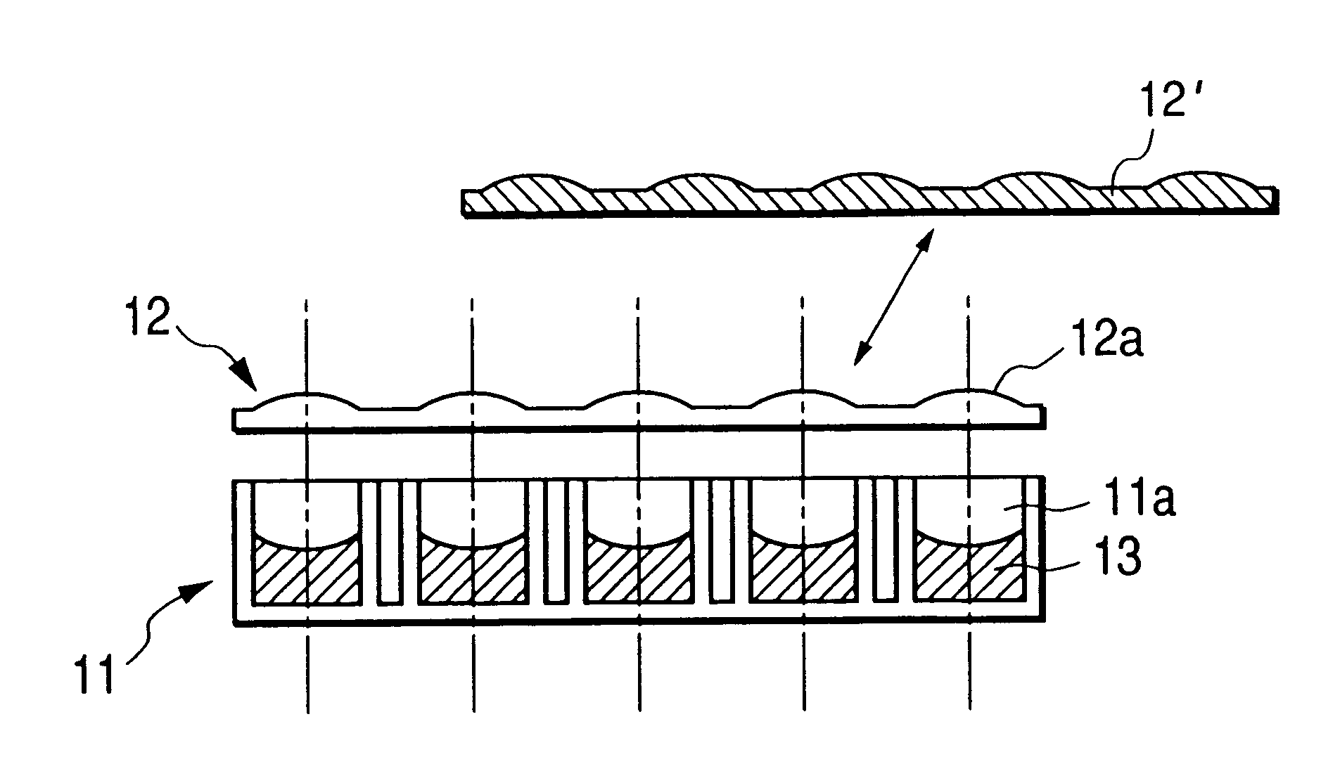
In Embodiment 1, the culture vessel is composed of a well plate 11 and a lens array 12 as shown in FIG. 3. A plurality of wells 11a are arranged on the well plates, and a culture medium 13 is filled in each well from circular openings for cultivation of cells.

The lens array 12 is disposed on the opening side of each well 11a, being arranged so as to allow a plurality of lenses 12a to confront the opening of each well 11a. Each of the lenses 12a has a positive refractive power and its optical axis is aligned so as to be approximately coaxial with the center line of the diameter of the respective confronting well 11a. The lens array 12 is made to maintain a relative position to the well plate 11 as shown in FIG. 3 by an appropriate means not shown in the drawing. The lens array 12 can be detached from the well plate 11 for taking the culture medium 13 in and out.

Since the culture vessel according to the present invention has a construction as hitherto described, the well plate 11 and ...

embodiment 2

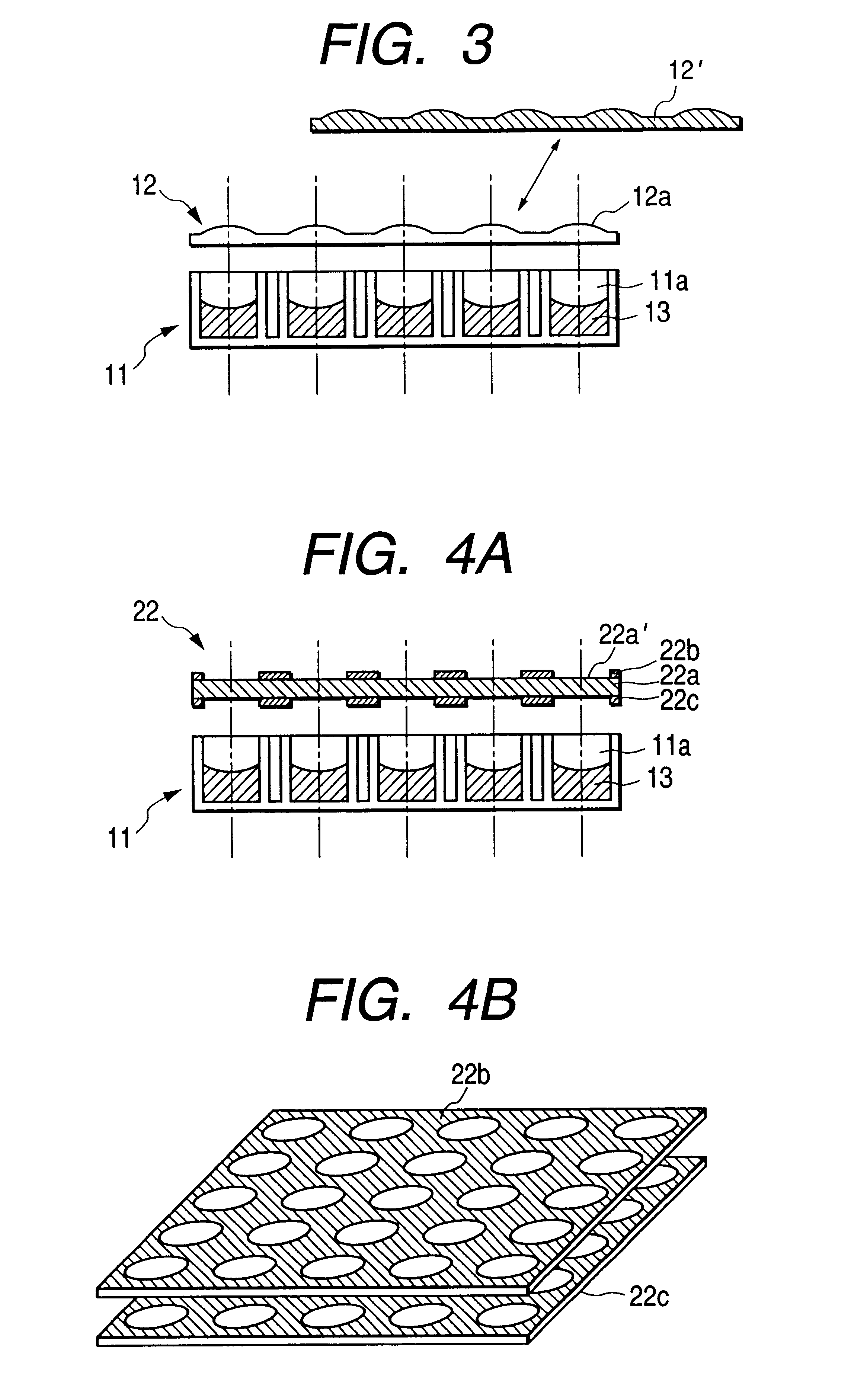
Embodiment 2 is explained referring to FIG. 4. FIG. 4A denotes a cross section showing the overall construction of the culture vessel according to the present invention while FIG. 4B is perspective views of two electrodes shown in FIG. 4A. The culture vessel according to this embodiment is composed of a well plate 11 and lens array 22. The same reference numerals are attached to the construction of the well plate 11 and culture medium 13 because they are exactly identical to those in Embodiment 1. Accordingly, precise descriptions of them are omitted.

The lens array used in this example is composed of liquid crystal lenses, electrodes 22b and 22c being attached on both faces of the liquid crystal 22a so as to leave a plurality of circular opening regions to serve as respective lenses 22a' behind. The optical axis of each lens 22a' is aligned to be approximately coaxial with the center line of the diameter of each well 11a. The focal distance of each lens 22a' in this lens array 22 is...

embodiment 3

Embodiment 3 is explained referring to FIG. 5. FIG. 5 is a cross section showing the overall construction of the culture vessel according to this embodiment, which is composed of a well plate 11 and lens array 32. Of this construction, since the construction of the well plate 11 and the culture medium 13 are the same as those in the foregoing embodiments, the same reference numerals are attached to them and their explanations are omitted. The lens array 32 in this embodiment is composed of liquid lenses, which is constructed of a parallel flat plate 32a, a parallel flat plate 32c on which elastic materials 32b are disposed in the plurality of opening regions to serve as lenses, and a liquid 32d filled between the parallel flat plates 32a and 32c.

Since the lens array 32 according to this embodiment is composed of liquid lenses, the positive refractive power of each lens can be corrected by changing the space between the two parallel flat plates 32a and 32c. In other words, the liquid...


PUM


Abstract

The present invention provides a culture vessel and microscope that allows a wide area of favorable observation of the sample in the plural wells even when a negative refractive power is generated in the culture medium, wherein a ring-shaped opening, a condenser lens, a lens array, a well plate, an objective lens and a phase contrast plate are disposed in this order viewed from the light source side with a construction to place a phase contrast film of the phase contrast plate in a conjugated relation to the projection pupil position or projection pupil of the objective lens, and the culture vessel is constructed of the lens array and well plate with a relative disposition in which the optical axis of each lens is coaxial with the center line of the confronting each well; the aperture of the ring-shaped opening being smaller than the aperture of the ring-shaped opening that is used when the culture vessel is not disposed in the optical path.

Description

1. Field of the InventionThe present invention relates to a culture vessel, and a microscope for observing the sample in the culture vessel.2. Description of the Related ArtA culture vessel manufactured by disposing a plurality of culture ponds (referred to a well hereinafter) with well-like shapes or concave shapes on a plate (referred to a well plate hereinafter) for cell culture has been known in the art. While a variety of inner diameters of the well are available, the number of the wells disposed on the well plate increases as the inner diameter of the well becomes smaller. A well plate on which wells with an inner diameter of 16.5 mm or less, or 24 or more of the wells, are disposed is practically used (for example, the Multi-well Plate 3047 and Micro-test Plate 3070 made by Becton Dikinson Co. have 24 wells and 96 wells, respectively).However, the range where a phase contrast effect is obtainable is limited to a central portion of the well when one attempts to observe the cel...

Claims


Application Information

Patent Timeline
IPC IPC(8): B01L3/00G01N21/25G02B21/34G01N1/10C12M1/00C12M1/34G02B21/00
CPCB01L3/50853G01N21/253G02B21/34C12M23/12C12M41/36G01N2201/0407
Inventor KASAHARA, TAKASHI
Owner OLYMPUS CORP
Why Eureka
Try Eureka