
Ink-jet printer with printing head cap

Inactive Publication Date: 2001-06-05
BROTHER KOGYO KK
View PDF16 Cites 15 Cited by
  • Summary
  • Abstract
  • Description
  • Claims
  • Application Information

AI Technical Summary

Benefits of technology

Another object of the present invention is to provide an ink-jet printer which makes it possible to allow a protective cap to make tight contact with a nozzle surface of a printing head when the protective cap is pressed against the printing head regardless of an inclination of a surface of the protective cap with respect to the nozzle surface of the printing head.
The ink-jet printer of the present invention has the swinging mechanism swinging the cap surface of the cap unit in response to the inclination of the printing head surface. Therefore, the condition of tight contact between the cap and the printing head is remarkably improved when the cap covers the nozzle surface of the printing head after the cap is moved by the cap-moving mechanism from a waiting position at which the cap is retracted from a passage for movement of the printing head to a protruding position at which the cap protrudes into the passage for movement of the printing head.
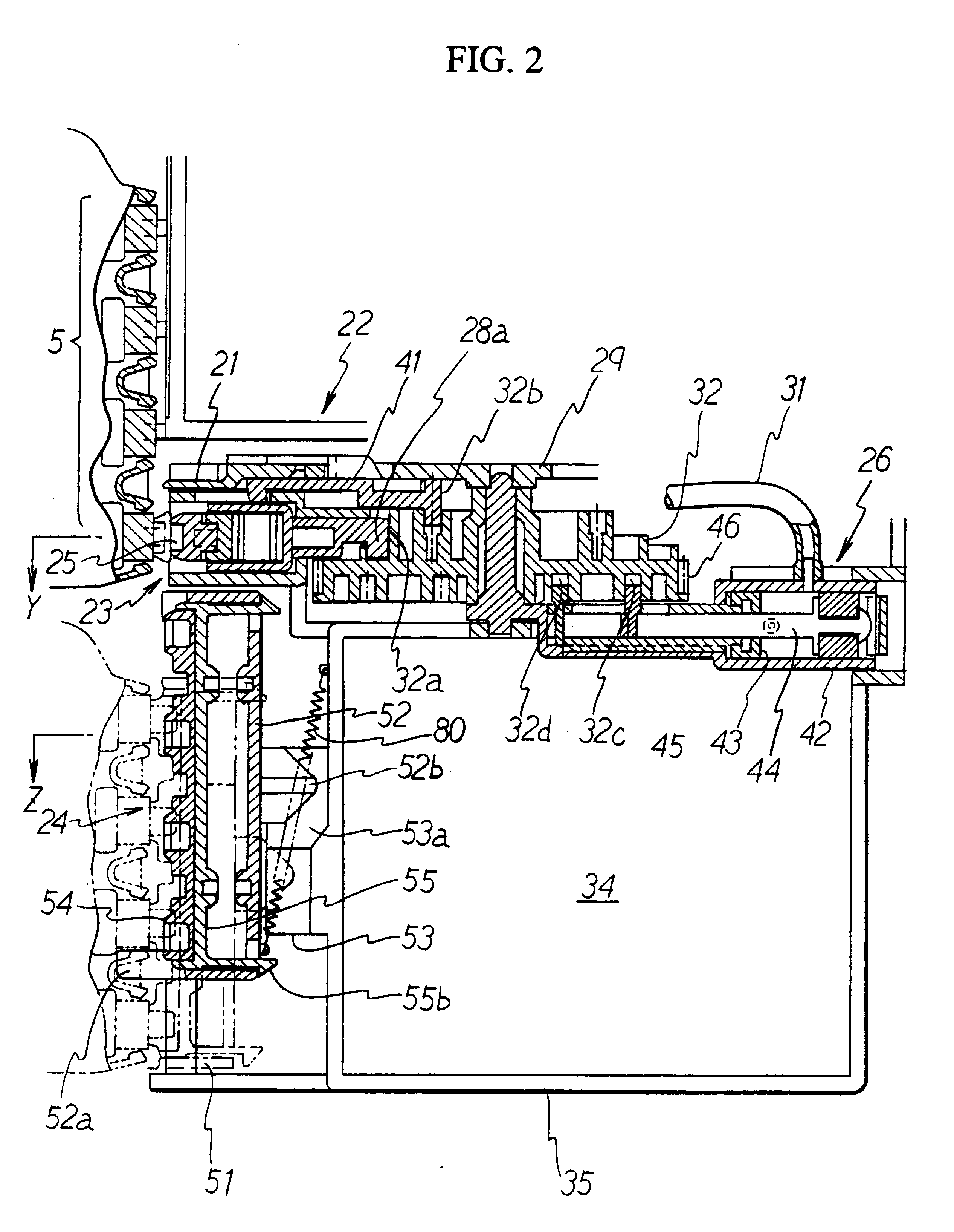
The cap holder may have an engaging projection at its front end and a fastening section avoiding disengagement from the casing at its back end respectively, and the casing may have a regulating projection disengageably engaging the engaging projection of the cap holder to regulate a relative positional relationship between the cap holder and the casing. By adopting such a structure, the cap holder is integrated with the casing by the aid of the urging force exerted by the resilient member when the cap is not pressed against the printing head. Accordingly, the cap held by the cap holder can be positioned with respect to the nozzle surface of the printing head with high positional accuracy when the casing makes sliding movement with respect to a frame member and the cap abuts against the nozzle surface.
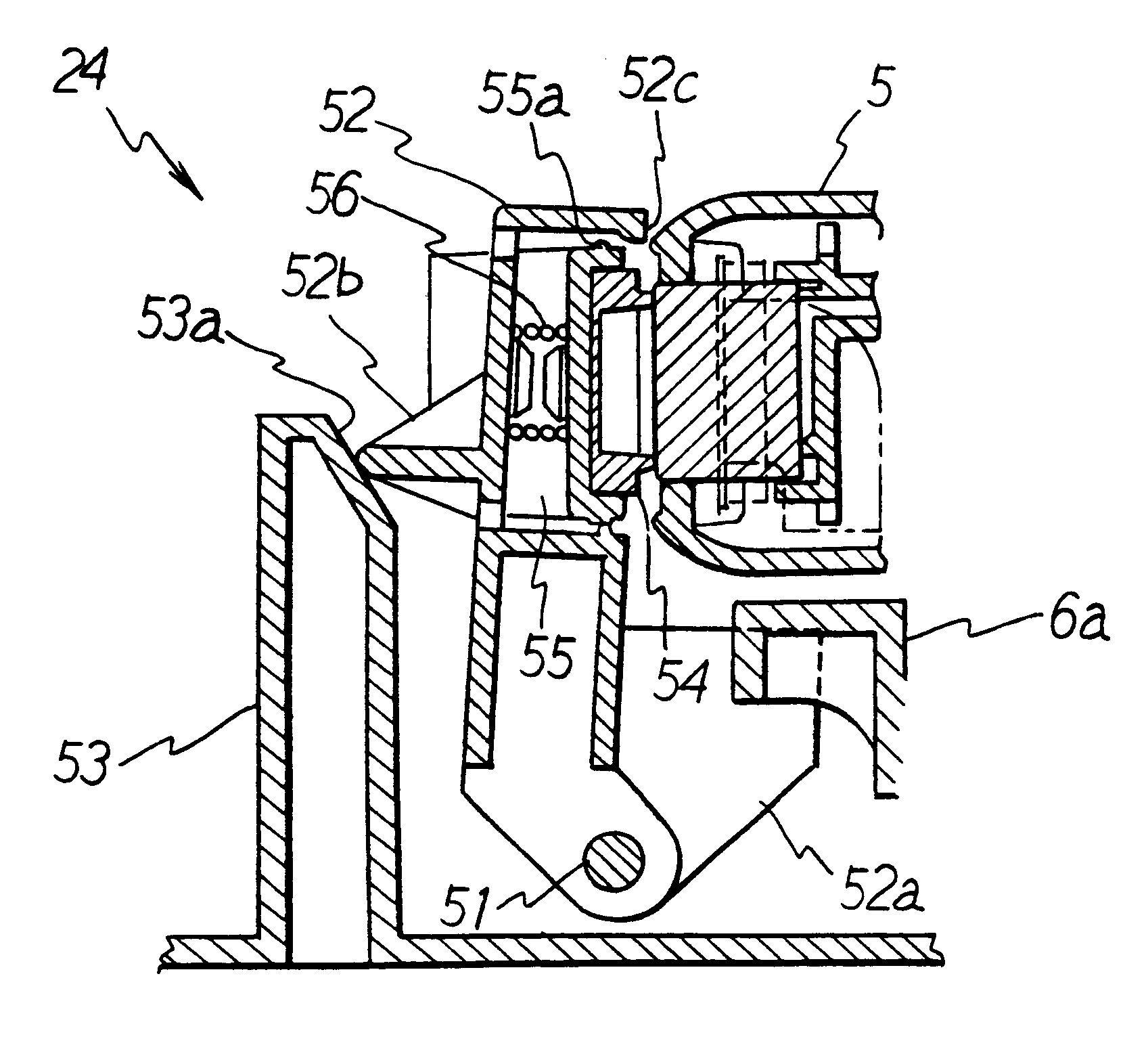
The cap of the cap unit to be used in the ink-jet printer of the present invention may be a protective cap covering the nozzle of the printing head to avoid evaporation of the ink. Because the protective cap can swing in response to an inclination of the surface of the printing head, the printing head can be reliably covered to avoid evaporation of the ink. In a preferred embodiment, the swinging mechanism may comprise a holding frame supporting the protective cap at the front end of the holding frame, a movable housing accommodating the holding frame with a play allowed to exist between the holding frame and the movable housing, and a resilient member connected to the holding frame so that the holding frame is urged toward the printing head. The holding frame is urged toward the printing head by the aid of the resilient member, and the movable housing accommodates the holding frame with the play allowed to exist between the holding frame and the movable housing. Accordingly, when the protective cap is non-uniformly pressed against the printing head, the front surface of the protective cap can swing to make tight contact with the surface of the printing head.
The holding frame may have an engaging projection at its front end and a fastening section avoiding disengagement from the movable housing at its back end respectively, and the movable housing may have a regulating projection disengageably engaging the engaging projection of the holding frame to regulate a relative positional relationship between the holding frame and the movable housing. By adopting a structure, the holding frame is integrated with the movable housing by the aid of the urging force exerted by the resilient member when the protective cap is not pressed against the printing head. Accordingly, the protective cap can be positioned with respect to the nozzle surface of printing head with high positional accuracy when the movable housing moves toward the printing head and the protective cap abuts against the nozzle surface.

Problems solved by technology

However, the ink-jet printer sometimes undergo ink-discharge failure or defective ink-discharge.
Such ink-discharge failure or defective ink-discharge is caused by various reasons including, for example, adhesion of dust to a nozzle tip for discharging ink droplets, immixture of bubbles in an ink supplied from an ink source, drying of the ink in a nozzle, and adhesion of paper dust from a recording medium to the nozzle during printing.
Therefore, if the cap surface of the suction cap has a low degree of parallelism with respect to the nozzle surface of the printing head, tight contact is poorly achieved when the suction cap is allowed to abut against the printing head, making it impossible to satisfactorily suck the ink from the nozzle.
Such an ink-jet printer has had a problem in that the ink is dried if tight contact is poorly achieved between the protective cap and the printing head.

Method used


Image

  • Ink-jet printer with printing head cap
  • Ink-jet printer with printing head cap
  • Ink-jet printer with printing head cap

Examples


Embodiment Construction

An embodiment of the present invention will be explained below with reference to the drawings.

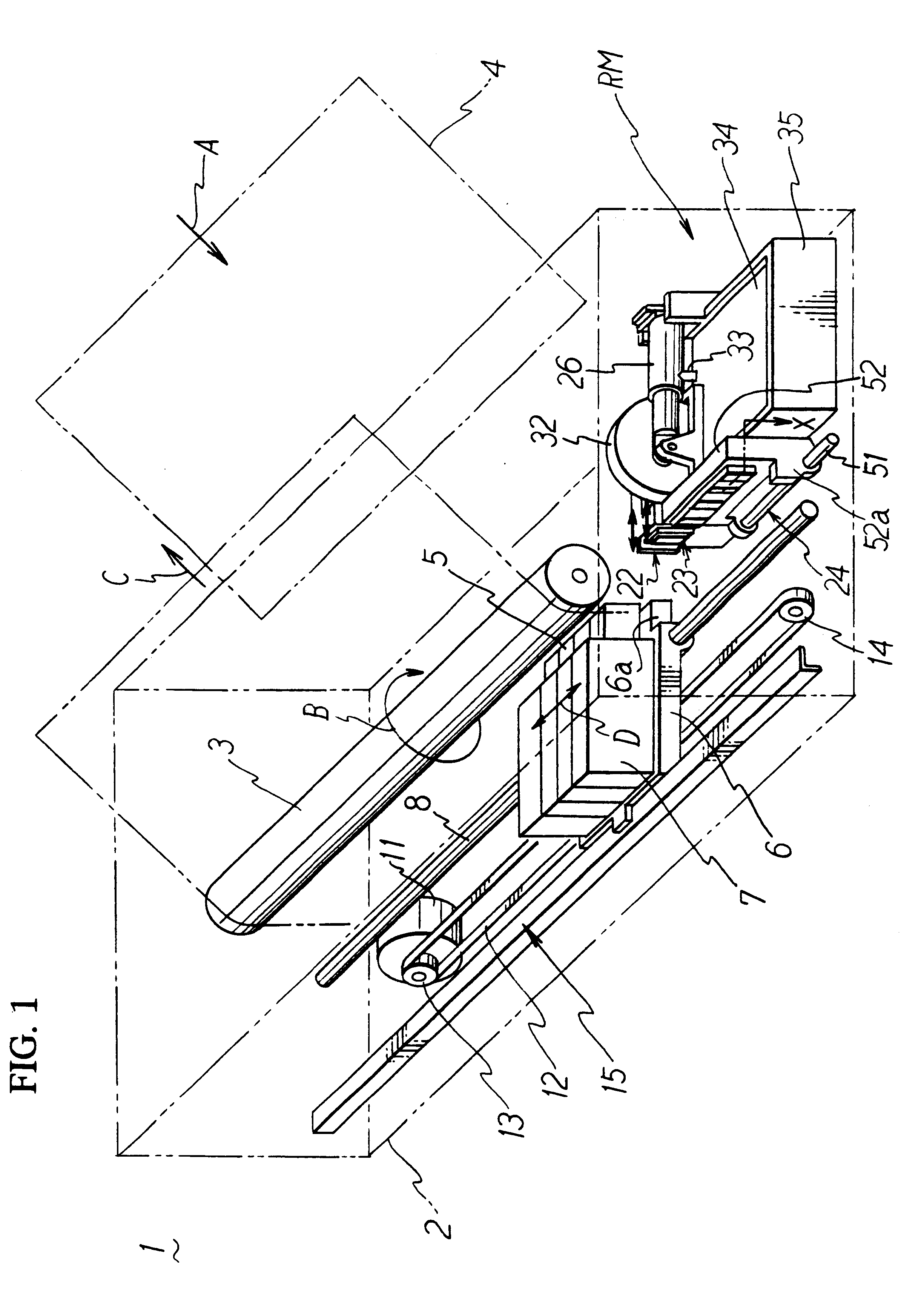
FIG. 1 shows a schematic perspective view of an illustrative ink-jet printer according to the present invention. The ink-jet printer 1 principally comprises printing heads 5 for the ink-jet printing, a carriage 6 for placing the printing heads 5 thereon, a carriage-moving mechanism for reciprocatively moving the carriage 6 in parallel to a surface of a sheet of printing paper 4, a platen roller 3 for feeding the printing paper 4, a restoring unit RM for restoring discharge failure of the printing heads 5, and a printer frame 2 for accommodating the foregoing. The platen roller 3 is a cylindrical roller rotatably supported on the printer frame 2 by the aid of a rotation shaft(not shown) extending in a longitudinal direction of the printer frame 2, i.e., extending laterally when the printer 1 is viewed from a position in front thereof. The printing paper 4 is supplied from a paper supply cass...


PUM


Abstract

An ink-jet printer has a suction cap for avoiding discharge failure of an ink from a printing head. When the printing head comes to a restoring area, the suction cap is moved from a waiting position at which the suction cap is retracted from a passage for movement of the printing head to a protruding position at which the suction cap protrudes into the passage for movement of the printing head. The suction cap covers a nozzle surface of the printing head. A purge unit is driven to suck the ink remaining in the printing head through the suction cap. The suction cap is supported by a casing so that the suction cap is swingable when it is pressed against the printing head. The suction cap makes tight contact with the printing head in response to the nozzle surface of the printing head

Description

The present invention relates to an ink-jet printer which has a purge unit for preventing ink-discharge failure or defective ink-discharge.DESCRIPTION OF THE RELATED ARTAn ink-jet printer is generally used for performing dot-matrix recording on a sheet of printing paper supplied and fed from a paper feeder by discharging ink droplets. However, the ink-jet printer sometimes undergo ink-discharge failure or defective ink-discharge. Such ink-discharge failure or defective ink-discharge is caused by various reasons including, for example, adhesion of dust to a nozzle tip for discharging ink droplets, immixture of bubbles in an ink supplied from an ink source, drying of the ink in a nozzle, and adhesion of paper dust from a recording medium to the nozzle during printing.Accordingly, in order to provide a restoring unit for dissolving the ink-discharge failure or the defective ink-discharge so that a normal state is restored, it has been hitherto known to provide a purge unit having a suc...

Claims


Application Information

Patent Timeline
IPC IPC(8): B41J2/165B41J2/175B41J2/18B41J2/185
CPCB41J2/16511
Inventor MURAKI, MOTOHITO
Owner BROTHER KOGYO KK
Learn More