Core sheet, core and method of manufacturing an armature

a technology of core and armature, which is applied in the direction of dynamo-electric machines, magnetic circuit rotating parts, magnetic circuit shape/form/construction, etc., can solve the problems of reluctance changes and cogging in the torque of the motor, and achieve less slipping out of the armature winding, less cogging in the torque, and high space factor

Inactive Publication Date: 2001-06-05
ASMO CO LTD
View PDF14 Cites 62 Cited by
  • Summary
  • Abstract
  • Description
  • Claims
  • Application Information

AI Technical Summary

Benefits of technology

It is another object of the present invention to provide an armature of an electric motor, which has a high space factor in each slot, less cogging in the torque and less slipping out of the armature windings.
It is a further object of the present invention to provide an improved method of manufacturing an armature of an electric motor, which increases efficiency of winding operation.
According to the present invention, an armature for a motor has a core, which comprises a plurality of core sheets stacked together in an axial direction. Each sheet has a plurality of teeth having an extended protrusion, which covers an armature winding fitted in slots. The extended protrusion is a pair of bendable long protrusion pieces on each tooth of one sheet, and a pair of bendable short protrusion pieces on each tooth of another sheet stacked adjacently to the one sheet. Alternatively, the extended protrusion is a pair of long protrusion piece and short protrusion piece on each tooth. The protrusion pieces are bent to cover the armature winding after winding operation, leaving only a narrow slit between the two extended protrusions. Thus, the slit is provided discontinuously in an axial direction of the core, so that cogging in torque of the motor is reduced.

Problems solved by technology

However, the widened slit is likely to cause cogging in the torque of the motor, because each slit 23 extends in the axial direction as a continuous line thereby causing reluctance changes at the same time.

Method used


Image

  • Core sheet, core and method of manufacturing an armature
  • Core sheet, core and method of manufacturing an armature
  • Core sheet, core and method of manufacturing an armature

Examples


first embodiment

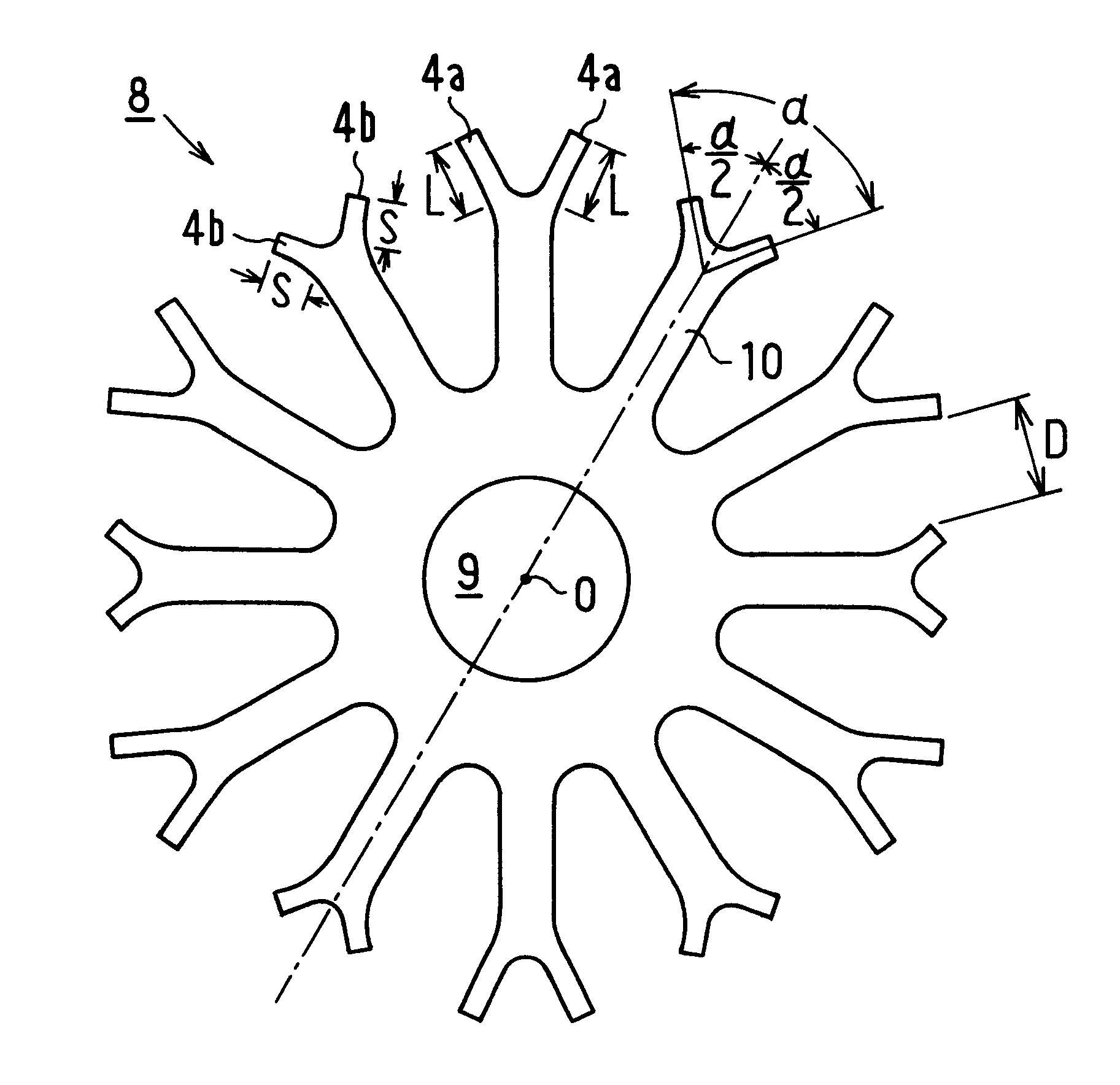
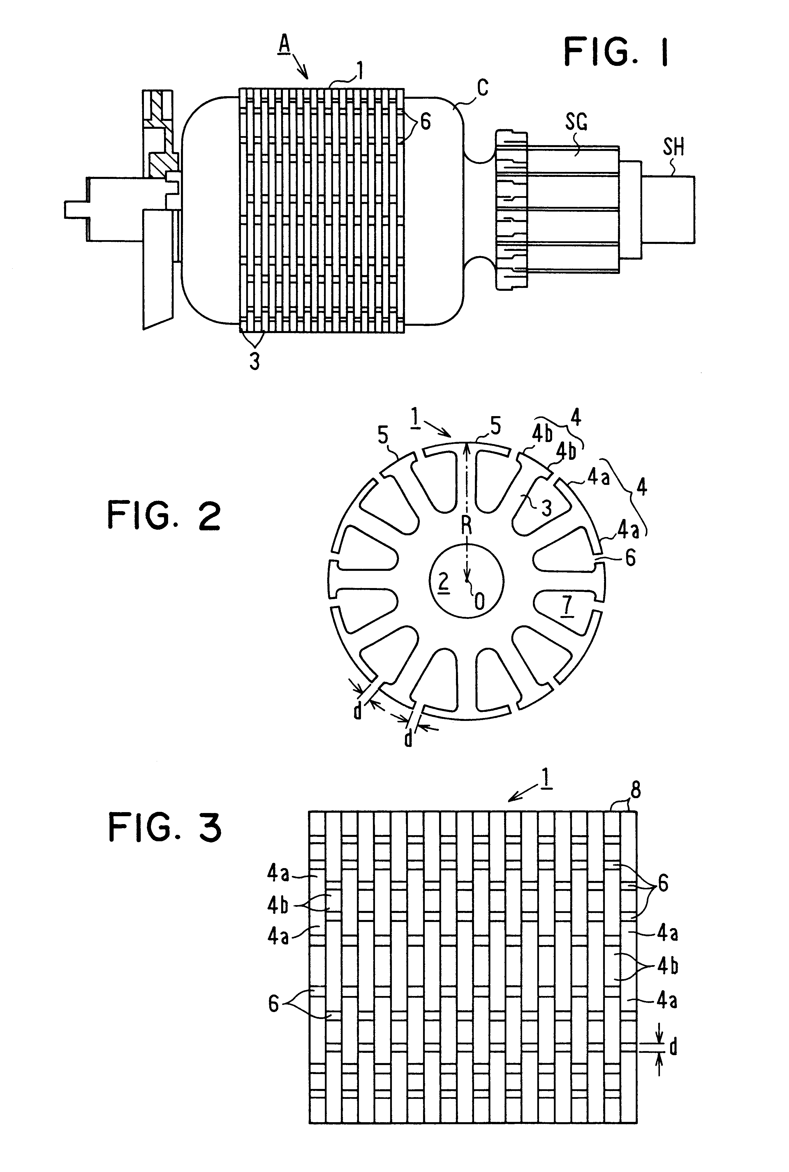
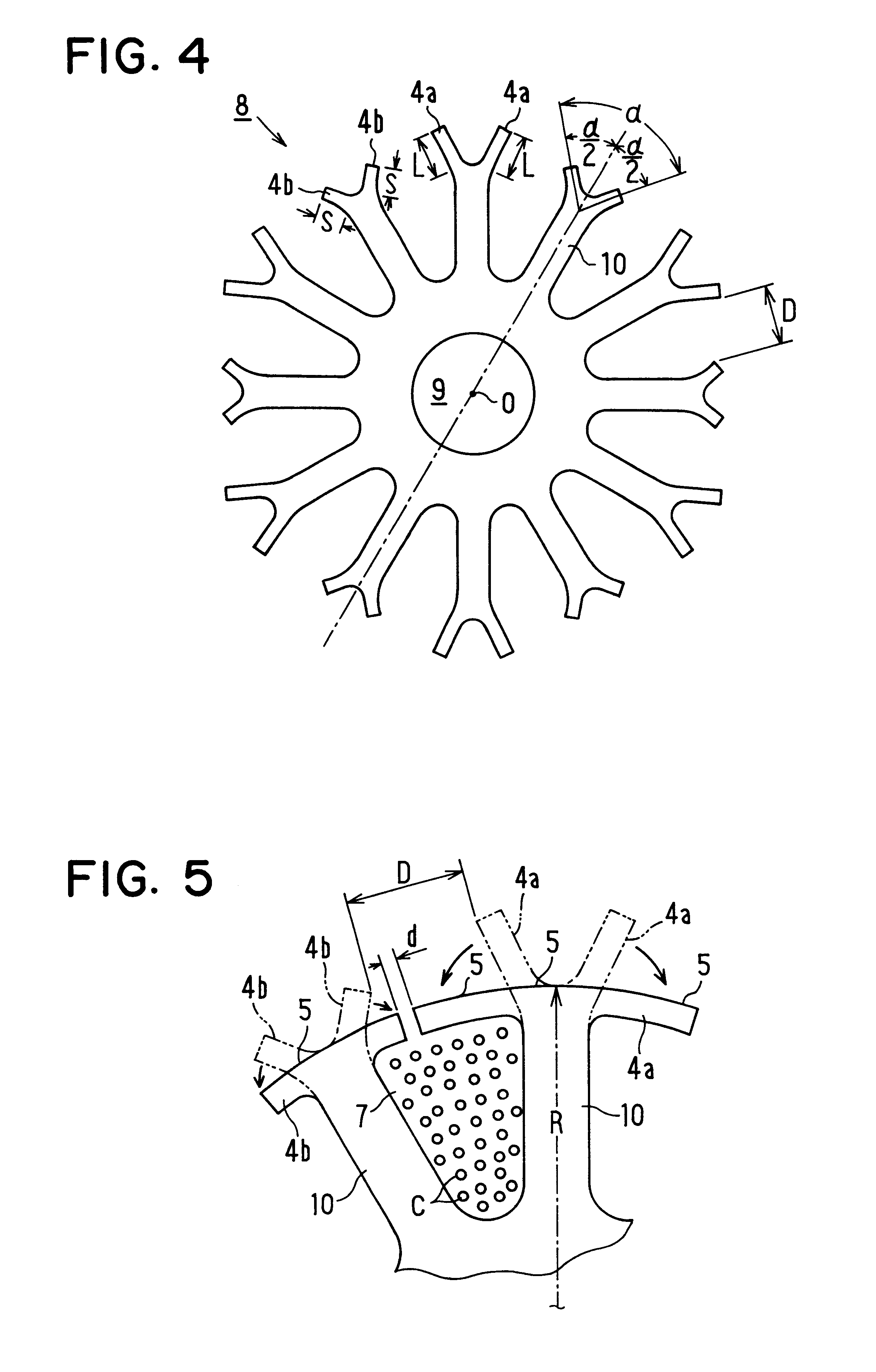
The first embodiment provides the following advantages. (1) As the armature winding C is inserted through the wide opening having the width D between the protrusion pieces 4a, 4b before bending, it can be wound from the radially inner part (root) of the tooth 3 toward the radially outer part of the same densely in the slot 7. Thus, space factor of the armature winding C in the slot 7 can be increased. (2) As the slit 7 is formed only after inserting the armature winding C in the slots 7, the width d of the slit 6 does not affect the winding inserting operation. Thus, the slit width d can be set as narrow as possible thereby to reduce cogging in the torque of the motor. (3) As each core sheet 8 is displaced in the circumferential direction by one slot from the adjacent core sheet 8 when stacked, the slits 6 are arranged in crossing manner thereby to equalize the magnetic flux distribution. As a result, the reluctance changes do not occur at the same time among core sheets 8 during th...

second embodiment

(Second Embodiment)

In this embodiment, as shown in FIG. 6, each core sheet 11 is shaped to have the teeth 10 in the same configuration.

That is, each tooth 10 has a pair of long protrusion piece 4a and short protrusion piece 4b in such a manner that the long protrusion piece 4a and the short protrusion piece 4b are arranged alternately in the circumferential direction. The core sheets 11 are stacked to provide the core 1 in such a manner that the front surface and the rear surface of each core sheet 11 contact with the front surface and the rear surface of the adjacent core sheet 11, respectively. That is, the long protrusion piece 4a and the short protrusion piece 4b of each core sheet 11 are in contact with the short protrusion piece 4b and the long protrusion piece 4b, respectively, in the axial direction of the core 1. Thus, the core 1 has the slits 6 between the long protrusion piece 4a and the short protrusion piece 4b as shown in FIG. 7. The slits 6 are not arranged on the sam...

third embodiment

(Third Embodiment)

In this embodiment, as shown in FIG. 8, each core sheet 13 has either a pair of long protrusion pieces 4a or a pair of short protrusion pieces 4b on each tooth 10 as in the first embodiment. However, the tooth 10 is formed a pair of cuts 14 at the root part of the protrusion pieces 4a, 4b. That is, the width of the tooth 10 at the root part of the protrusion pieces 4a, 4b is narrowed by the cuts 14 as shown in FIG. 9. This third embodiment also provides the same advantages (1) to (5) as in the first and second embodiments. In addition, the cuts 14 enables easy bending of the protrusion pieces 4a, 4b in the direction to close the slots 7, thereby improving the efficiency of protrusion piece bending work.


PUM


Abstract

An armature for a motor has a core, which comprises a plurality of core sheets stacked together in an axial direction. Each sheet has a plurality of teeth having an extended protrusion which covers an armature winding fitted in slots. The extended protrusion may be a pair of bendable long protrusion pieces on each tooth of one sheet, and a pair of bendable short protrusion pieces on each tooth of another sheet stacked adjacently to the one sheet. Alternatively, the extended protrusion may be a pair of long protrusion piece and short protrusion piece on each tooth. The protrusion pieces are bent to cover the armature winding after winding operation, leaving only a narrow slit between the two extended protrusions. The slit is discontinuous in an axial direction of the core. Thus, the armature winding is restricted from slipping out from the slots, and cogging in torque of the motor is reduced.

Description

CROSS REFERENCE TO RELATED APPLICATIONThis application relates to and incorporates herein by reference Japanese Patent Application No. 10-55154 filed on Mar. 6, 1998.BACKGROUND OF THE INVENTION1. Field of the InventionThe present invention relates to a core sheet, core and method of manufacturing an armature using the core sheet.2. Related ArtIn a conventional electric motor, as shown in FIGS. 19, 20, 21, an armature 20 has a rotary shaft SH at its radial center. A core 21 wound with armature windings C is fixed to the rotary shaft SH together with commutator SG. The core 21 comprises a plurality of stacked core sheets 22, each of which is a thin magnetic steel plate. The core 21 has on its outer peripheral surface a plurality of slits 23, each of which extends in parallel with the rotary shaft SH. The slit 23 has a slit width d in the circumferential direction of the core 21.The core sheet 22 has a plurality of T-shaped teeth 24 extending in the radial direction from its radial cen...

Claims


Application Information

Patent Timeline
Patent Type & Authority Patents(United States)
IPC IPC(8): H02K3/493H02K3/48H02K1/26H02K3/487H02K15/02
CPCH02K3/493
Inventor UEMURA, KEIICHIYAMAMOTO, TOSHIO
Owner ASMO CO LTD
Why Eureka
Try Eureka