Connected structure and method for manufacturing the same

a technology of connecting structure and manufacturing method, which is applied in the direction of manufacturing tools, transportation and packaging, and other domestic objects, and can solve the problems of thermal fatigue, poor joint between, and deterioration of the efficiency of utilizing the surrounding spa

Inactive Publication Date: 2001-06-12
SUMITOMO RIKO CO LTD +1
View PDF13 Cites 16 Cited by
  • Summary
  • Abstract
  • Description
  • Claims
  • Application Information

AI Technical Summary

Benefits of technology

Another object of the present invention is to provide a method for manufacturing a connected structure in which the manufacturing efficiency can be improved.
If the friction agitation joining method is performed by using a coining device having a pin-shaped probe coaxially integrally protruded from an end surface of a columnar rotor having a diameter larger than a diameter of the prove, inserting the rotating probe into the connecting portion from the hollow supporting member to soften and agitate a portion where the probe contacts by friction heat, rotating the connecting portion and the hollow supporting member against the rotating probe in such a state that the end surface of the columnar rotor presses a downstream portion of the supporting member and is lifted up from an upstream portion of the supporting member, the efficiency of joining work can be also improved by the same reasons as described above. Further, since the end surface of the rotor is lifted up from the surface of the upstream portion of the supporting member, an edge of the end surface of the rotor facing the upstream portion of the supporting member can be prevented from being caught by the surface of the supporting member so as not to tear off the surface while the connecting portion and the supporting member rotate. As a result, a connected structure with fine joint quality can be obtained.

Problems solved by technology

Such a rectangular cross-sectional shape of the supporting portion 51 inherently deteriorates the efficiency for utilizing the surrounding space.
Further, such a large heat quantity may cause a poor joint between the supporting body 51 and the bushing mounting body 52, and / or a thermal fatigue of the supporting body 51 and the bushing mounting body 52.
If the entire end surface 32 of the rotor 31 is inserted into the supporting member 1 or further into the connecting portion 13 in order to enlarge the contact area, the edge of the end surface of the rotor 31 will be caught by the matrix of the upstream portion of the rotating supporting member 1, resulting in a suspension arm having a poor joint quality.

Method used


Image

  • Connected structure and method for manufacturing the same
  • Connected structure and method for manufacturing the same
  • Connected structure and method for manufacturing the same

Examples


Embodiment Construction

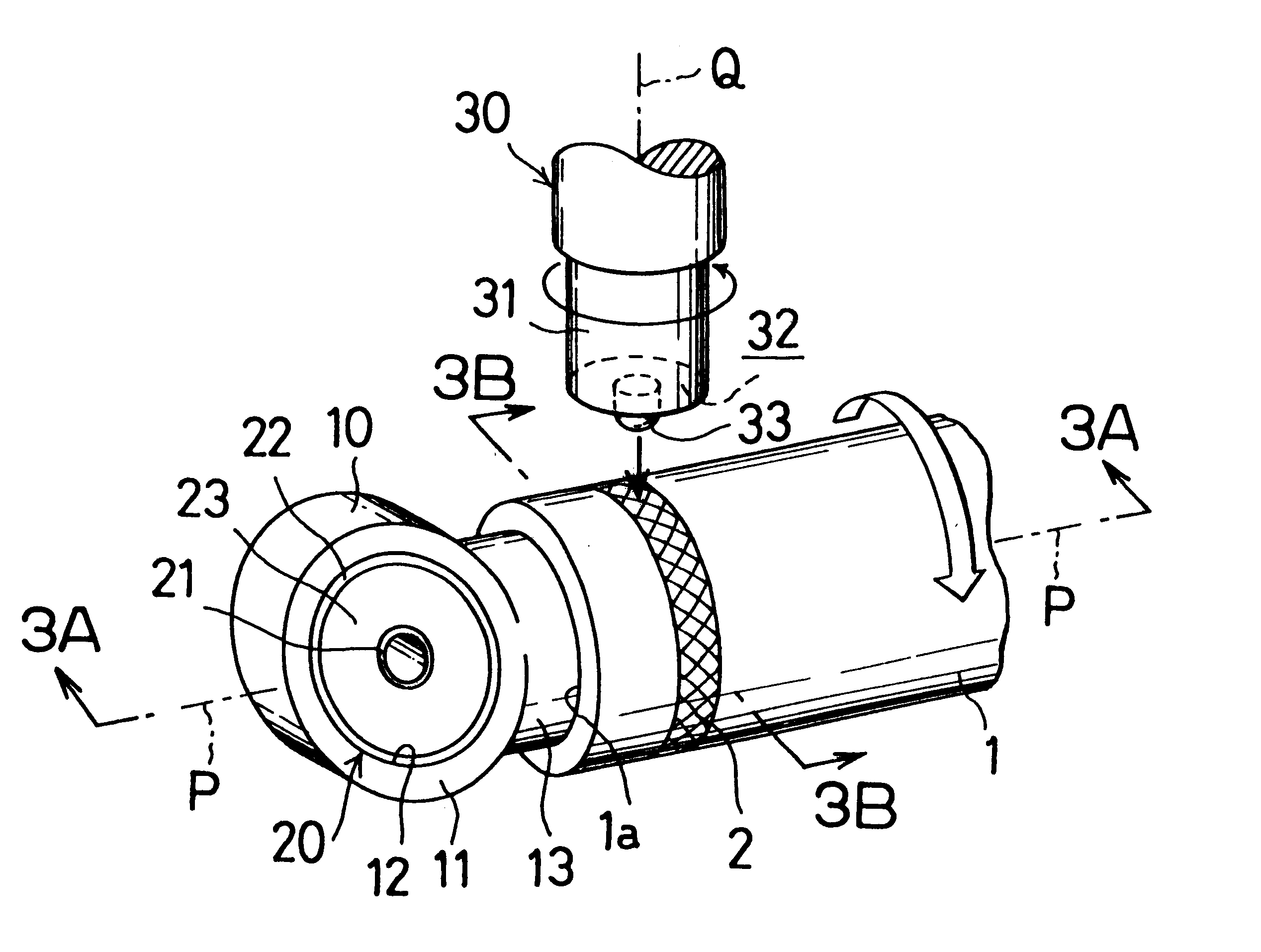
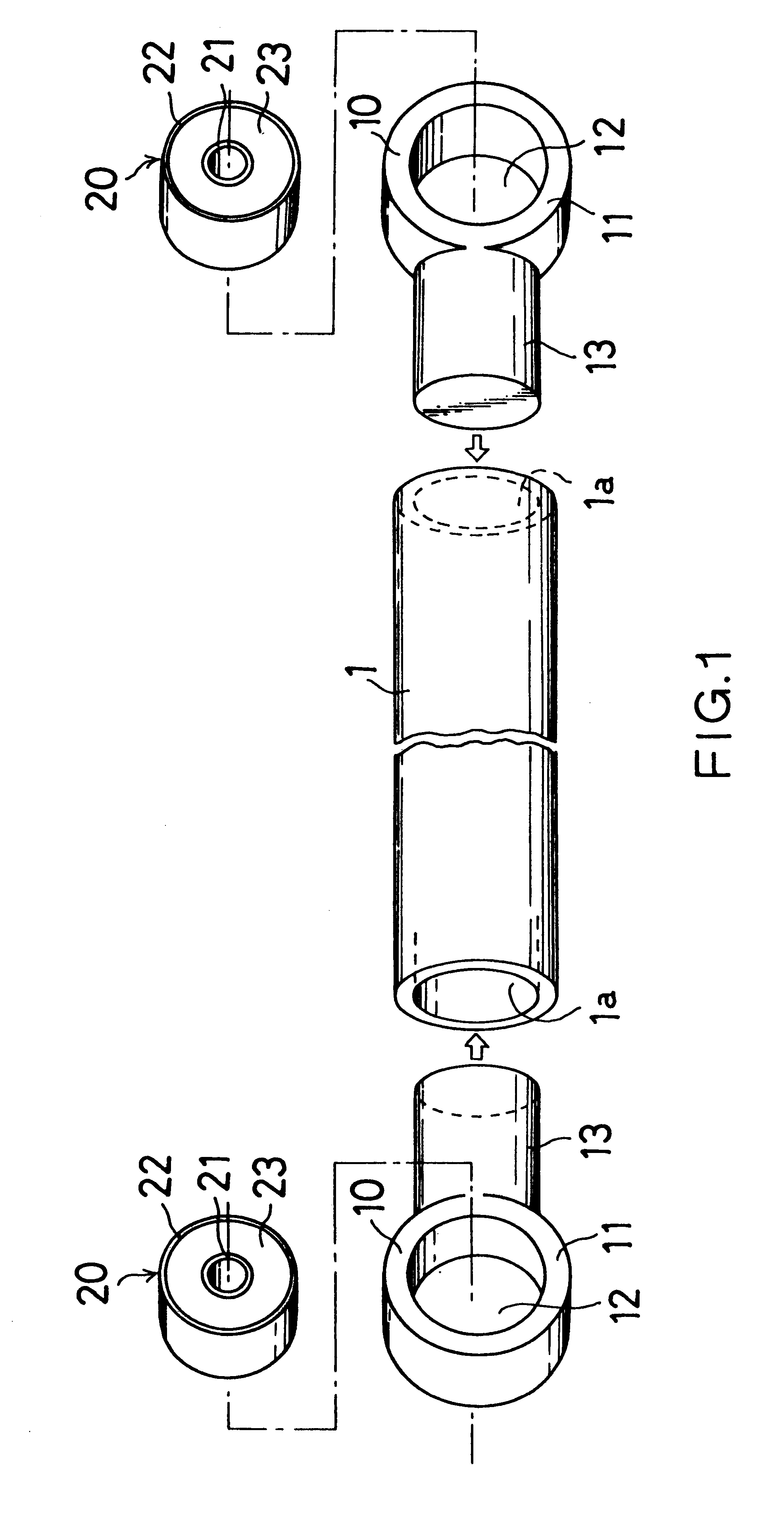
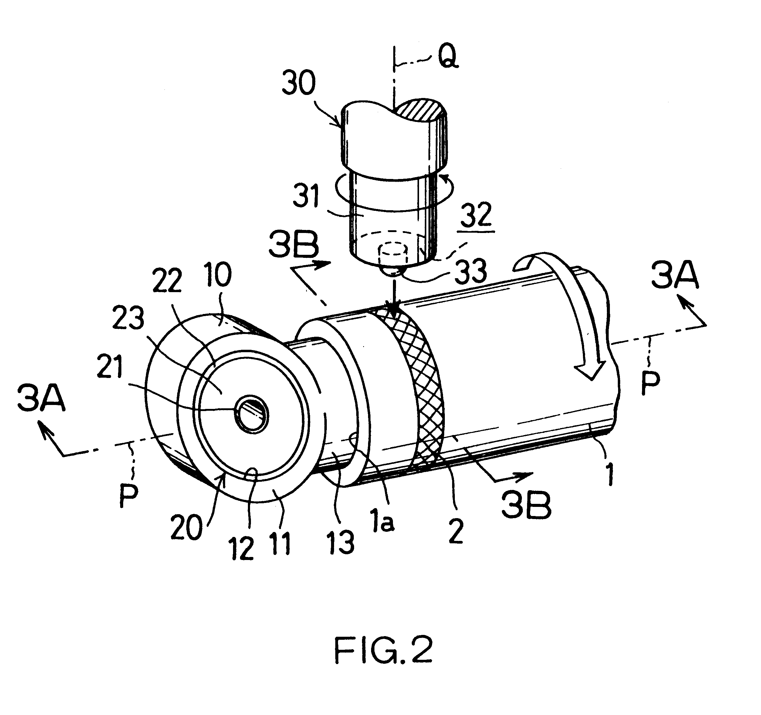
In order to manufacture the connected structure for use as a suspension arm as shown in FIGS. 1 to 55, the supporting members 1 and the bushing mounting members 10 are made from JIS (Japanese Industrial Standard) A6061 aluminum alloy, respectively. The connecting portion 13 of the bushing mounting member 10 is inserted into the opening 1a of the supporting member 1, and the coupled portion of the connecting portion 13 and the supporting member 1 is joined along a circumference of the supporting member 1 by a friction agitation joining method to obtain the connected structure according to the present invention, which is referred to as an Example. On the other hand, in Reference, the joining was performed by a TIG welding method. The highest temperature in the opening 12 of the bushing mounting member 10 during the joining process and the joint efficiency were measured. These results were shown in the TABLE 1 as follows.

As shown in TABLE 1, the highest temperature of the Example was l...


PUM

PropertyMeasurementUnit
outer diameteraaaaaaaaaa
relative angleaaaaaaaaaa

Abstract

A connected structure includes a supporting member and a bushing mounting member connected thereto. The supporting member is made of a pipe having a round cross-sectional shape. The bushing mounting member includes a bushing mounting portion for mounting a bushing having a rubber elastic member and a connecting portion protruded from the bushing mounting portion. The connecting portion is press-fitted into an opening at one end of the supporting member, and the connecting portion and the supporting member are joined together along a circumference of the supporting member by a friction agitation joining method. Accordingly, the connecting member which is light in weight and high in strength with an improved efficiency for utilizing the surrounding space and a predetermined characteristics of a bushing can be obtained.

Description

1. Field of the InventionThis invention relates to a connected structure, more particularly, to a connected structure including a supporting member and a bushing mounting member connected thereto for use as, for example, an automobile suspension arm or an engine mount.2. Description of the Related ArtFIG. 8A shows a conventional automobile suspension arm 50 used as an upper arm, a lower arm, a trailing arm or a torsion arm. The suspension arm 50 includes a rod-shape supporting portion 51 and a bushing mounting portion 52 formed at opposite ends of the supporting portion 51. The bushing mounting portion 52 may be formed at one end of the supporting portion 51. The bushing mounting portion 52 has a circular opening 53 for mounting a columnar vibroisolating bushing 60. The bushing 60 includes, for example, a central supporting member 61, an outer rigid sleeve 62 having an outer diameter slightly larger than the inner diameter of the opening 53, and a rubber elastic member 63 disposed b...

Claims


Application Information

Patent Timeline
Patent Type & Authority Patents(United States)
IPC IPC(8): B23K20/12B60G7/00B23K103/10F16F1/38
CPCB23K20/129B60G7/001B23K2201/04B23K2201/06B60G2206/11B60G2206/1112B60G2206/8201B60G2206/82013B23K2101/04B23K2101/06
Inventor KATO, RENTAROUCHINO, KOJIOGAWA, YUICHIENOMOTO, MASATOSHITASAKI, SEIJINISHIKAWA, NAOKIKAWATA, NAOYUKIHASHIMOTO, TAKENORI
Owner SUMITOMO RIKO CO LTD
Why Eureka
Try Eureka